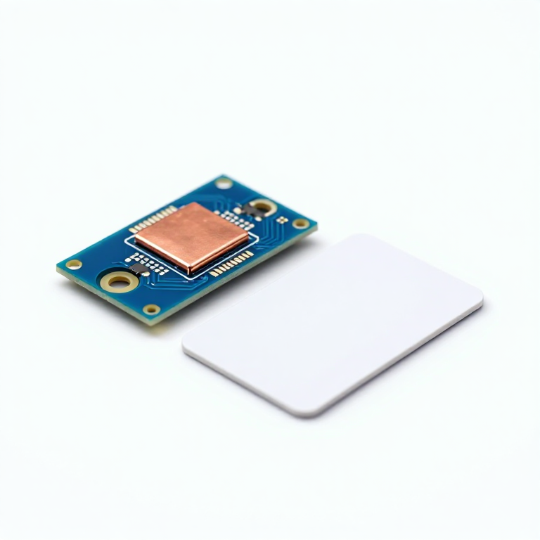


RFID Access Reader
안내
Assemble the relay board
Assemble the relay board
The Beefcake board ships as a kit and has to be soldered before anything else.
- Fit the relay, the screw terminals and the passives.
- Check the coil side and the contact side are on the correct halves of the board before applying power.
이 단계의 재료:
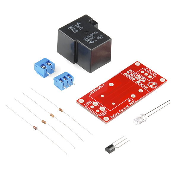 SparkFun Beefcake Relay Control Kit1 키트
필요한 도구:
 Ryobi ONE+ RSI18-0 Cordless Soldering Iron
Mount the reader module and wire it — pin by pin
Mount the reader module and wire it — pin by pin
Fit the SM130 and its antenna to the 13.56 MHz evaluation shield, then wire the shield to the Arduino.
- SM130 TX → Arduino D2 (Arduino receives)
- SM130 RX → Arduino D3 (Arduino transmits)
- SM130 VCC → 5V, GND → GND
- Relay board control input → Arduino D7, its GND to Arduino GND
The SM130's UART is 5 V and 5 V tolerant, so it connects straight to an Uno with no level converter. That is specific to this module — the 3.3 V SM5210 parts do need one.
Never wire the module's UART pins to an RS232 port directly. RS232 swings around ±12 V and will destroy it; a USB-UART adapter is required.이 단계의 재료:
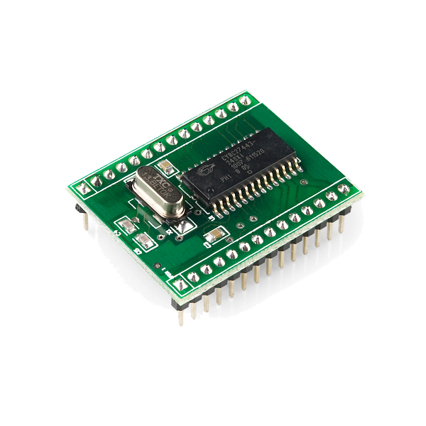 RFID Module - SM130 Mifare (13.56 MHz)1 개
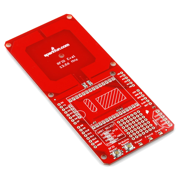 RFID Evaluation Shield - 13.56MHz1 개
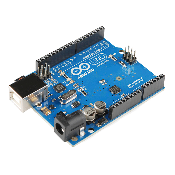 Arduino Uno R3 SMD1 개
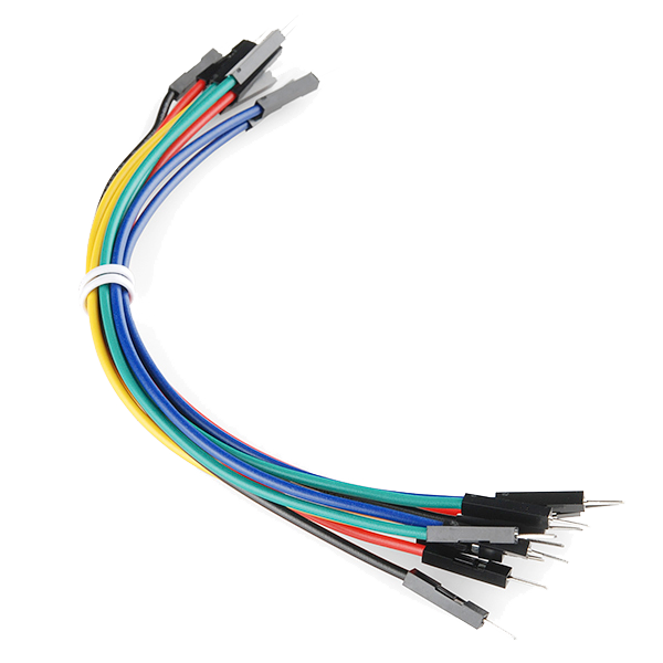 Jumper Wires Premium M/M 20 AWG - 15.5 cm (Pack of 10)1 팩
Configure the module for Auto Mode with ASCII output
Configure the module for Auto Mode with ASCII output
Out of the box the module is in Standard Mode, where it waits for binary commands. Put it into Auto Mode with ASCII output instead, using SonMicro's Mifare Panel tool over a USB-UART adapter.
- Set Operation Mode to Auto Mode (Automatic Card Reading).
- Under Auto Read Mode set Serial Output Type to ASCII, and tick CR and LF.
- Leave Baudrate at its factory 19200.
That combination is the stock template 02/AUTO-B-P-ASCII-CRLF, so it can also be ordered pre-configured, or applied from a supplied .xml upgrade file with no configuration step at all.
Auto Mode is what makes this project simple. The module reports each card as a line of plain text the moment it enters the field, so the Arduino never has to build a framed binary packet or verify a checksum.이 단계의 재료:
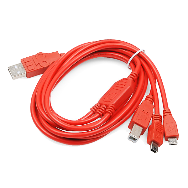 USB-B Cable1 개
Read a card and write its identifier down
Read a card and write its identifier down
Power the Arduino over USB, open the serial monitor at 9600, and upload the sketch from the next step with the allow-list still empty.
- Present a tag. A line of hex digits appears.
- Write that identifier down exactly as printed.
- Repeat for every card that should be allowed.
이 단계의 재료:
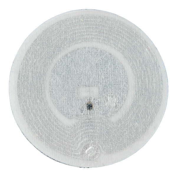 RFID Tag - Adhesive Mifare 1K (13.56 MHz)2 개
Upload the access sketch
Upload the access sketch
Put the identifiers you recorded into the ALLOWED array, then upload. SoftwareSerial ships with the IDE — nothing else is needed.
Test the reject path before the accept path
Test the reject path before the accept path
Present an unlisted card first, and confirm the relay stays shut and the monitor prints denied.
- Only then present a listed card and confirm it opens.
- Wire the strike through the relay's normally-open contact, so a power cut leaves the door secure rather than released.
재료
7- 1 키트₩102
- 1 개₩364
- 1 개₩261
- Arduino Uno R3 SMD10% 수수료1 개₩364
- 1 개₩76
- ₩48
필요 도구
1- ₩1,253
CC0 퍼블릭 도메인
이 블루프린트는 CC0로 공개되었습니다. 어떤 목적으로든 자유롭게 복사, 수정, 배포 및 사용할 수 있습니다.
제품 구매를 통해 메이커를 지원하세요. 판매자가 설정한 메이커 커미션 을 받거나, 이 블루프린트의 새로운 반복을 만들어 연결로 포함시킬 수 있습니다.