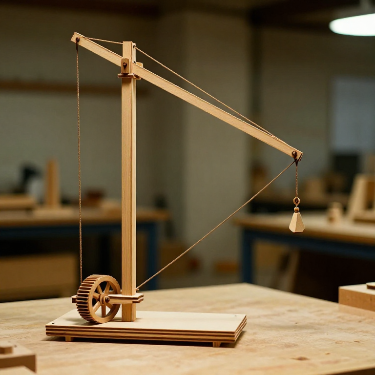
Building a Roman Treadwheel Crane Model — Ancient Construction Machinery
안내
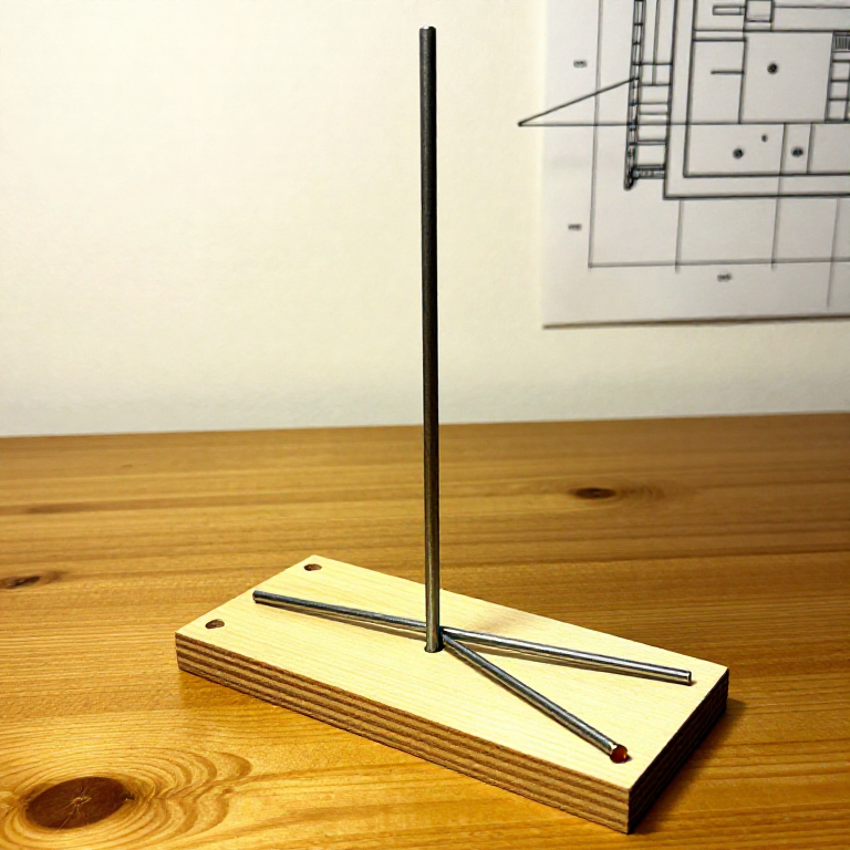
Build the Mast and Base
Build the Mast and Base
Cut a vertical mast from a 6 mm hardwood dowel, approximately 25 cm tall. Glue it vertically into a hole drilled in the centre of the base board, reinforcing with two diagonal braces (shorter dowels cut to approximately 12 cm) glued from the mast to the base at about 45 degrees on opposite sides. These braces correspond to the stay-beams that Vitruvius calls the 'retinaculae' — they prevent the mast from toppling under load. The mast must be perfectly vertical (check with a small plumb line). At the top of the mast, drill a horizontal hole through the dowel to accept a pivot pin for the boom (jib) attachment. The full-scale Roman crane mast was typically a single timber 8 to 12 metres tall, held upright by guy ropes on three or four sides.
이 단계의 재료:
 Basswood Sheet1 piece 20 x 20 cm cm
 Wood Gluesmall amount 개
Construct the Boom and Pulley Block
Construct the Boom and Pulley Block
Cut the boom (jib) from a 6 mm dowel, approximately 20 cm long. Attach one end to the top of the mast with a pin through the drilled hole, allowing the boom to pivot up and down. At the far (free) end of the boom, mount a compound pulley block — drill axle holes through two small wooden discs (2 cm diameter) and mount them side by side on a short pin, with the pin attached to the boom tip by a small wooden bracket. These paired pulleys represent the trochlea (pulley block) that Vitruvius describes. On the mast near the top, mount another pair of pulleys. The rope will weave between these two pulley sets to create a mechanical advantage. In a real compound pulley with four sheaves, the mechanical advantage is 4:1 — meaning one unit of pulling force lifts four units of load weight (minus friction losses).
이 단계의 재료:
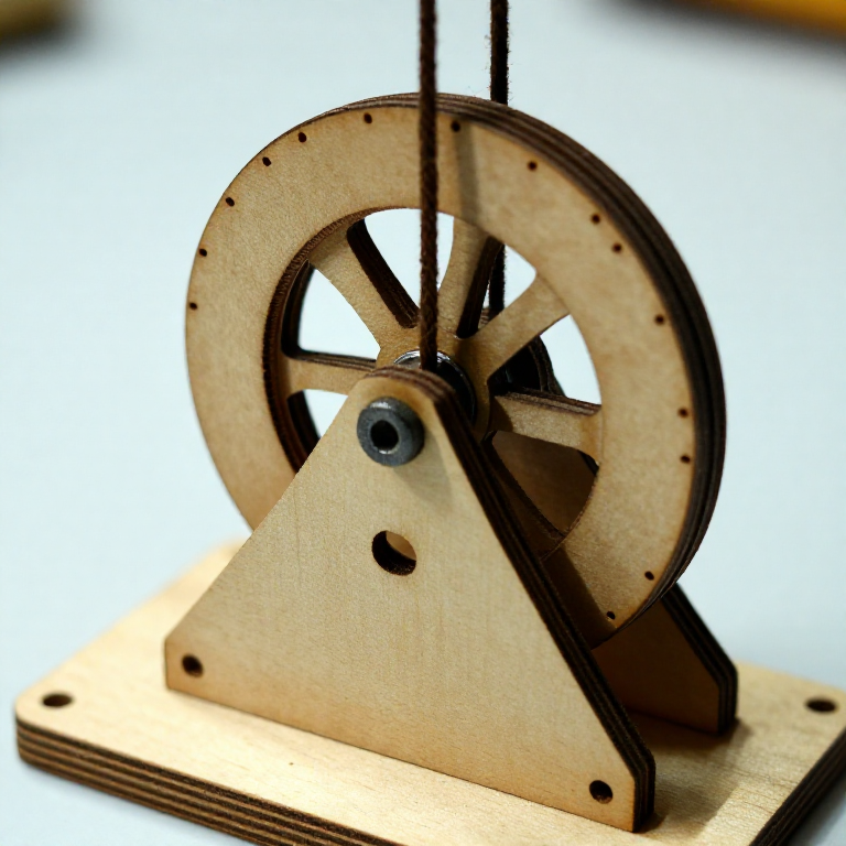
Basswood Sheet1 piece 20 x 20 cm cmWood Gluesmall amount 개Build the Treadwheel
Build the Treadwheel
Cut a circle approximately 12 to 15 cm in diameter from the thin plywood — this represents the treadwheel drum. Drill a centre hole and mount it on a horizontal axle (a nail or pin) supported by two upright brackets attached to the base board behind the mast. The treadwheel must rotate freely on its axle. Glue small wooden pegs or strips around the interior circumference to represent the treading steps. In a full-scale Roman treadwheel (diameter approximately 4 to 5 metres), workers walked inside the wheel like a hamster wheel, and their body weight turning the wheel wound the rope onto the axle drum. The mechanical advantage of the treadwheel itself is the ratio of the wheel radius to the drum (axle) radius — a 2.5-metre radius wheel with a 15 cm radius drum provides approximately 16:1 advantage, multiplied by the pulley ratio.
이 단계의 재료:
Basswood Sheet1 piece 20 x 20 cm cmWood Gluesmall amount 개Rig the Rope Through the Pulleys
Rig the Rope Through the Pulleys
Thread the cord through the pulley system following the standard compound pulley path: tie one end to the fixed upper pulley block bracket, pass it down and around the first lower (boom-tip) pulley, back up to the second upper pulley, down to the second lower pulley, and then lead the free end down to the treadwheel drum where it is tied and wound several turns around the axle. Attach a small hook or loop to the lower pulley block for hanging loads. The rope path should run cleanly without crossing or tangling. When the treadwheel turns, it winds the rope onto the drum, pulling the rope through the pulleys and lifting the load. With a four-sheave compound pulley, every metre of rope wound onto the drum lifts the load by 25 centimetres — the trade-off between force and distance that defines all simple machines.
Test and Demonstrate Mechanical Advantage
Test and Demonstrate Mechanical Advantage
Hang a small weight (such as a bag of coins or a fishing sinker) from the hook on the lower pulley block. Turn the treadwheel slowly by spinning it with a finger — the load should rise smoothly. Compare the effort required to lift the same weight directly versus through the compound pulley — the pulley system should make the load feel significantly lighter, though the rope must be pulled a longer distance. This demonstrates the fundamental principle of mechanical advantage that Roman engineers exploited at massive scale. The Haterii relief (a 1st-century funerary monument in Rome) depicts a Roman treadwheel crane in operation, showing the scale and complexity of these machines. Vitruvius notes that a crane with a compound pulley and treadwheel operated by just a few men could lift loads that would require dozens of labourers pulling directly on a rope.
재료
7- 1 sheet 개플레이스홀더
- 1 piece 개플레이스홀더
- several 개플레이스홀더
CC0 퍼블릭 도메인
이 블루프린트는 CC0로 공개되었습니다. 어떤 목적으로든 자유롭게 복사, 수정, 배포 및 사용할 수 있습니다.
제품 구매를 통해 메이커를 지원하세요. 판매자가 설정한 메이커 커미션 을 받거나, 이 블루프린트의 새로운 반복을 만들어 연결로 포함시킬 수 있습니다.