Push Buttons — SIK Circuit 5
안내
Parts & Introduction
Parts & Introduction
Push buttons are the simplest digital input. This experiment uses two buttons with an XOR logic gate: the LED turns on if you press either button, but turns off if you press both. You'll learn about digitalRead(), pull-up resistors, and boolean logic.
Parts Needed
- 1x Arduino Uno + USB cable
- 1x Breadboard
- 2x Push Buttons
- 1x LED (any color)
- 1x 330Ω Resistor
- 2x 10KΩ Resistors (pull-ups)
- 7x Jumper Wires
이 단계의 재료:
 SparkFun Inventors Kit - V3.21 키트
 Arduino Uno R31 개
 Breadboard1 개
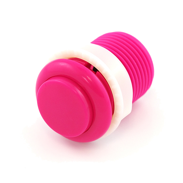 Push Button2 개
 5mm LED1 개
 330 Ohm Resistor1 개10K Ohm Resistor2 개
 Jumper Wires7 개
필요한 도구:
Hardware Hookup
Hardware Hookup
Wiring Instructions
- Place both push buttons across the center canyon of the breadboard.
- Button 1: Connect one pin to GND. Connect the opposite diagonal pin to Arduino Digital Pin 2. Add a 10K resistor between Pin 2 and 5V (pull-up).
- Button 2: Connect one pin to GND. Connect the opposite diagonal pin to Arduino Digital Pin 3. Add a 10K resistor between Pin 3 and 5V (pull-up).
- Connect LED positive leg to Digital Pin 13, negative leg through 330Ω resistor to GND.
Note: The pull-up resistors hold the input HIGH when the button is not pressed. Pressing the button connects the pin to GND (LOW).
이 단계의 재료:
Push Button2 개5mm LED1 개330 Ohm Resistor1 개10K Ohm Resistor2 개Breadboard1 개Jumper Wires7 개Arduino Code
Arduino Code
Open the Arduino IDE and upload the following sketch to your Arduino board.
/*
SparkFun Inventor's Kit
Example sketch 05 — PUSH BUTTONS

Use pushbuttons for digital input.
LED on if pressing button 1 OR button 2, but not both (XOR).

Hardware connections:
  Button 1: one pin to GND, diagonal pin to digital pin 2
            10K pullup resistor between pin 2 and 5V
  Button 2: one pin to GND, diagonal pin to digital pin 3
            10K pullup resistor between pin 3 and 5V
  LED: positive to pin 13, negative through 330 ohm to GND

This code is completely free for any use.
*/

const int button1Pin = 2;
const int button2Pin = 3;
const int ledPin = 13;

void setup()
{
  pinMode(button1Pin, INPUT);
  pinMode(button2Pin, INPUT);
  pinMode(ledPin, OUTPUT);
}

void loop()
{
  int button1State, button2State;

  button1State = digitalRead(button1Pin);
  button2State = digitalRead(button2Pin);

  // XOR logic: on if either pressed, off if both pressed
  if (((button1State == LOW) || (button2State == LOW))
      && !
      ((button1State == LOW) && (button2State == LOW)))
  {
    digitalWrite(ledPin, HIGH);
  }
  else
  {
    digitalWrite(ledPin, LOW);
  }
}
이 단계의 재료:
Arduino Uno R31 개필요한 도구:
Test & Experiment
Test & Experiment
What You Should See
The LED turns on when you press either button individually. It turns off when you press both buttons simultaneously (XOR logic).
Troubleshooting
- Not responding: Push buttons are square — it's easy to put them in the wrong orientation. Try rotating 90°.
- LED always on or always off: Check the pull-up resistor connections. Without them, the input pin floats and reads random values.
Experiments to Try
- Change the logic to AND (both buttons required) or simple OR.
- Use the buttons to control an RGB LED — one button for color, one for brightness.
- Try using
INPUT_PULLUPmode to eliminate the external resistors.
재료
8- ₩1,530
- 플레이스홀더
- 1 개플레이스홀더
- ₩17
CC0 퍼블릭 도메인
이 블루프린트는 CC0로 공개되었습니다. 어떤 목적으로든 자유롭게 복사, 수정, 배포 및 사용할 수 있습니다.
제품 구매를 통해 메이커를 지원하세요. 판매자가 설정한 메이커 커미션 을 받거나, 이 블루프린트의 새로운 반복을 만들어 연결로 포함시킬 수 있습니다.