예술
뷰티 및 웰니스
공예
문화 및 역사
엔터테인먼트
환경
음식 및 음료
역공학
과학
스포츠
기술
웨어러블


The Peristaltic Pump: Two Places Closed at Once, and No Valve Touches the Fluid
Squeeze a hose shut between two fingers and slide them along it: the liquid ahead is pushed forward, and the hose springs back behind your fingers and fills again. That is the whole of a peristaltic pump. A rotor carries rollers round a curved track, each pinching a flexible tube shut and rolling along it.
Nothing but the inside of the tube ever touches the liquid. There are no valves to clog, no seals to leak and nothing to clean except a tube that can be thrown away. That is why this is the pump for blood, for cell cultures, for dosing chemicals into a water supply, for concrete and for printer ink.
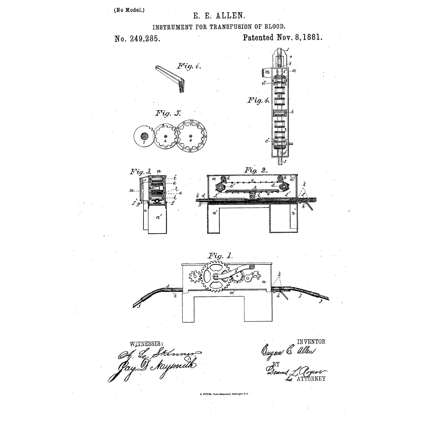
Rufus Porter and J. D. Bradley patented it in 1855 as a well pump, and wrote down the one rule every peristaltic pump still has to obey: the tube must be closed at **two places at the same instant**. In 1881 Eugene Allen used the same principle to move blood, precisely because it has no valves for blood to clot on. This rung builds one on a stepper motor.
중급
About 6 hours
안내
1
1
Choose the tube first — it sets everything else
Choose the tube first — it sets everything else
The tube is the pump. Its bore decides the flow per turn, its wall decides how hard the rollers must squeeze, and its material decides what it can carry and how long it lasts.
Use **silicone** tubing for this build: it recovers its round shape quickly after each pinch, which is what refills the pocket behind the roller. Clear PVC tubing is cheaper and stiffer — it recovers more slowly, takes a permanent flat set sooner and suits only slow, occasional duty.
Measure the inside diameter and the wall thickness with calipers, on a cut end, at several points round the circle. A tube squeezed flat is exactly **two walls thick**; that is the starting gap between roller and track. Write both numbers down — the track is designed around them in the next step.
이 단계의 재료:
 실리콘 튜브1 미터
필요한 도구:
 디지털 캘리퍼스 6인치
2
2
Print the track, the rotor and the rollers
Print the track, the rotor and the rollers
Print a housing with a curved track of 25 mm radius to the tube's centreline, wrapping **at least 180 degrees** — a U-shape with the tube entering on one leg and leaving on the other. Print a three-arm rotor that fits the stepper motor's 5 mm shaft with a grub screw, and fit a skateboard bearing on a machine screw at the end of each arm as a roller. Rolling bearings instead of fixed pegs is the difference between a pump and a tube cutter: a peg drags along the tube and wears through it.
Make the track a separate part held by two screws in slotted holes, so you can move it towards the rotor. That adjustment is the **occlusion** — how hard the tube is squeezed — and it is the only setting the pump has.
Clamp the tube at both ends of the track with printed clips, or it will creep round with the rollers until it is pulled tight and stops pumping.
이 단계의 재료:
 PETG 필라멘트120 g
 스케이트보드 베어링3 개
 기계 나사10 개
 스테퍼 모터1 개
필요한 도구:
 FDM 3D 프린터디지털 캘리퍼스 6인치
 육각 렌치 세트
 무선 드릴
무선 드릴 드릴 비트 세트
3
3
Flow per turn, and the two-closed-places rule
Flow per turn, and the two-closed-places rule
Jupyter 노트북 불러오는 중…
4
4
The drive: a stepper, a speed knob and a reverse button
The drive: a stepper, a speed knob and a reverse button
A stepper motor is the right drive for a dosing pump: it turns a known angle per step, so the volume pumped is simply steps counted. This sketch reads a potentiometer for speed and a button to reverse — reversing is how you clear an air lock or empty a line back into its bottle. Set the driver's current limit before connecting the motor; a stepper run at the wrong current either stalls under the tube's resistance or overheats.
peristaltic_drive.inoarduino
이 단계의 재료:
 Arduino Uno R31 개
 스테퍼 모터 드라이버1 개
 가변저항기1 개
 점퍼 와이어1 세트
 직류 전원 장치1 개
필요한 도구:
 Arduino IDE가 설치된 컴퓨터
5
5
Set the occlusion and calibrate against a column of water
Set the occlusion and calibrate against a column of water
Start with the track backed off so the rollers barely touch the tube. Put the inlet in a beaker of water with a drop of dye, lead the outlet into a graduated cylinder and run the pump slowly.
Move the track in a little at a time. At first the pump delivers almost nothing: the rollers push the liquid forward and it slips back past them. When the gap reaches about twice the wall thickness the flow jumps. Now raise the outlet a metre above the inlet and watch the dye: if it creeps backward between roller passes, close the track a little more. Stop as soon as it holds.
Do not go further than that. Every extra fraction of a millimetre crushes the tube on every pass and shortens its life, and gives no more flow.
Now calibrate: count 100 turns into the cylinder, divide, and compare with the notebook's figure. The real pump delivers less, because the tube does not fully recover its round shape between rollers. That measured number, not the calculated one, is what a dosing pump runs on.
이 단계의 재료:
 물1 리터
물1 리터 식용 색소 (흐름 가시화용 염료)1 방울
필요한 도구:
 눈금 실린더
 스톱워치육각 렌치 세트
 줄자
줄자6
6
Pulses and tube wear
Pulses and tube wear
Jupyter 노트북 불러오는 중…
7
7
The flow has drifted: find out why
The flow has drifted: find out why
A peristaltic pump's flow is only as good as its tube and its occlusion. These are the faults that change the calibrated millilitres per turn, in the order to check them.
Flow
Loading...
8
8
History and context
History and context
**US 12,753, 'Elastic-Tube Pump', Rufus Porter of Washington DC and J. D. Bradley of Brattleboro, Vermont, dated 17 April 1855.** Porter was the founder of Scientific American. The patent describes vulcanized india-rubber hose — only commercially available for a decade at that point — fixed round a cylindrical surface and traversed by a roller, and it names the condition that makes the pump work: the hose must be *"closed at the same instant"* in two places. One way they gave of doing it was to coil the hose a whole turn.
**US 249,285, 'Instrument for Transfusion of Blood', Eugene E. Allen of Grand Rapids, Michigan, filed 23 June 1881, granted 8 November 1881.** A rubber hose about an eighth of an inch in bore laid on a rubber cushion in a small brass box, with three or more glass rollers carried on an endless belt so that one always pressed it shut. Allen's specification says why: the moving pressure *"dispens[es] with all suction-valves, which, on account of the sticky and fibrinous nature of blood, will always clog and produce clots"*.
The roller pump went on to move blood in heart-lung and dialysis machines for the same reason Allen gave.
**Honest limits.** It pulses. Its flow depends on a tube that wears, so it drifts and must be re-calibrated. It is limited in pressure by what the tube can seal against — a few bar for ordinary laboratory tubing. And a worn tube does not fail gracefully: it splits, and whatever it was carrying ends up in the pump head.
재료
12- 1 미터플레이스홀더
- 120 g플레이스홀더
- 스케이트보드 베어링10% 수수료3 개플레이스홀더
- 10 개플레이스홀더
- 부터₩361
- 부터₩190
- 1 개플레이스홀더
- 1 리터플레이스홀더
- 플레이스홀더
관련 블루프린트
이 블루프린트들은 지식을 공유합니다 — 기술, 재료 또는 원리
Building Ctesibius' Force Pump — The First Double-Acting Piston Pump
Emma 작성
역학
111
0
0
0
3
0
One Way Only: The Check Valve and the Bang It Makes
Martin 작성
공구
18
0
0
0
0
0
Vulcanizing Rubber with Sulfur — The Accidental Discovery That Put Tyres on the Road
Charlie 작성
산업용
89
0
0
0
3
0
The Hose and Its Clip: Why It Was Tight When You Fitted It
Martin 작성
공구
14
0
0
0
0
0
The Plastic Blood Bag
Mary 작성
의학
41
0
0
0
0
0
The Centrifugal Pump: Speed Squared, and Why It Cannot Lift Air
Emma 작성
역학
14
0
0
0
0
0
CC0 퍼블릭 도메인
이 블루프린트는 CC0로 공개되었습니다. 어떤 목적으로든 자유롭게 복사, 수정, 배포 및 사용할 수 있습니다.
제품 구매를 통해 메이커를 지원하세요. 판매자가 설정한 메이커 커미션 을 받거나, 이 블루프린트의 새로운 반복을 만들어 연결로 포함시킬 수 있습니다.