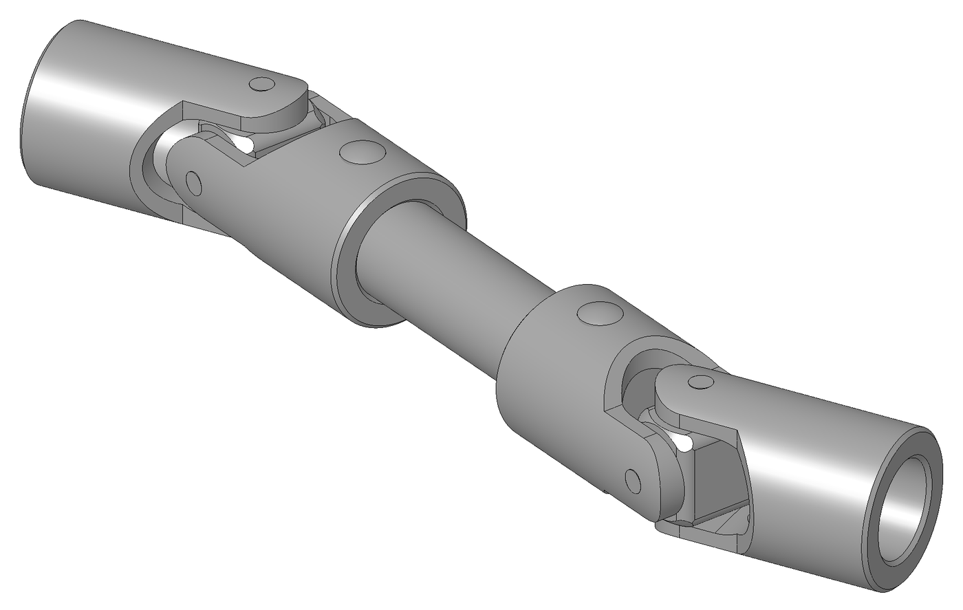


Universal Joint
안내
Make the cross
Make the cross
Four arms at 90 degrees, all the same length from centre. This part decides everything.
- Cut two 70 mm lengths of 25 mm aluminium round bar, or use 20 × 20 mm square bar for easier clamping.
- Mark the exact centre of each and cross-drill one 8.1 mm through, square to the bar.
- Cut a half-lap in each so the two cross at their centres and sit flush.
- Join them with a single M4 × 30 socket head cap screw through the lap, M4 flat washer × 2, M4 nylon insert lock nut × 1.
- Check with the caliper that all four arm ends are equidistant from the centre, within 0.2 mm.
이 단계의 재료:
 알루미늄 환봉1 개
 육각 홈붙이 원통 머리 볼트1 개
 평와셔2 개
 나일론 인서트 로크 너트1 개
필요한 도구:
 쇠톱 프레임과 톱날
 바이스(만력)
 무선 드릴
무선 드릴 드릴 비트 세트
 줄 세트
줄 세트 디지털 캘리퍼스 6인치
 센터 펀치
센터 펀치Cut the two yokes
Cut the two yokes
Each yoke is a U that straddles one pair of cross arms.
- Cut two strips 120 × 30 mm from 6 mm aluminium flat bar.
- Bend each into a U with 45 mm between the inside faces, or make each yoke from two separate arms bolted to a hub if bending 6 mm is beyond your vise.
- Drill both arms of each yoke together at 5.0 mm so the holes are coaxial.
- Deburr every hole.
Drilling both arms in one setup is what makes the axis straight. Drill them separately and the two holes will not line up; the cross then binds at one end of its swing and the joint feels notchy rather than smooth.
If you bolt rather than bend, use two M4 × 16 socket head cap screws per yoke into the hub with M4 flat washers, and check squareness with the combination square before final tightening.이 단계의 재료:
 알루미늄 평각봉1 개육각 홈붙이 원통 머리 볼트4 개평와셔8 개
필요한 도구:
바이스(만력)무선 드릴드릴 비트 세트 조합 직각자줄 세트
Assemble the joint and mount the shafts
Assemble the joint and mount the shafts
Two yokes, one cross, four pivots — and the two yokes must end up 90 degrees apart.
- Fit yoke 1 over one pair of cross arms using M5 × 30 socket head cap screws × 2 as pivot pins, with M5 flat washers × 4 and M5 hex nuts × 2.
- Fit yoke 2 over the other pair the same way — it will naturally sit at 90 degrees to the first.
- Mount each yoke on a shaft of 25 mm aluminium round bar.
- Support each shaft in a 608 bearing set into a plywood pillow block, so the input runs level and the output can be angled.
- Make the output block's mounting holes SLOTTED so you can set 0, 15 and 30 degree angles.
이 단계의 재료:
알루미늄 환봉1 개 발트 자작나무 합판1 장평와셔8 개
 육각 너트4 개
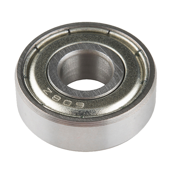 Ball Bearing - Non-Flanged (8mm Bore, 22mm OD)2 개
필요한 도구:
 육각 렌치 세트무선 드릴드릴 비트 세트
 실톱(코핑 소)디지털 캘리퍼스 6인치
Measure the velocity error you were told about
Measure the velocity error you were told about
This is the step that turns a familiar part into an understood one.
- Fit paper protractor discs to both shafts and align both at zero.
- Set the output at 0 degrees. Turn the input in 30 degree steps and record the output angle each time.
- Set 15 degrees and repeat. Then 30 degrees.
- For each run, plot output angle minus input angle.
이 단계의 재료:
발트 자작나무 합판1 팩필요한 도구:
조합 직각자디지털 캘리퍼스 6인치The two-joint cure, and history
The two-joint cure, and history
The standard fix is not a better joint — it is a second one. Put two universal joints in a driveshaft with equal operating angles and the yokes of the intermediate shaft in the same plane, and the second joint's error exactly cancels the first's. The output then turns at constant velocity even though neither joint does individually. Get the phasing wrong by 90 degrees and the errors ADD instead, which is a real and common cause of driveline vibration.
History. Gerolamo Cardano described the gimbal suspension in 1545 — hence Cardan joint — though as a mounting for compasses and lamps rather than a drive. Robert Hooke built and analysed the joint in the 1670s and identified the velocity variation, which is why it is also called a Hooke joint and why the error is sometimes called Hooke's coupling error.
Where each approach fits: a universal joint handles ANGULAR misalignment cheaply and takes real torque, at the cost of velocity error that grows with angle. An Oldham coupling handles PARALLEL offset at constant velocity but no angle at all. A true constant-velocity joint — the Rzeppa design in every front-wheel-drive car — solves both at once and costs far more to make. Three answers to misalignment, and the right one depends entirely on which kind of misalignment you have.
Why tractors are dangerous here: a power take-off shaft runs a universal joint at whatever angle the implement sits, and the velocity error becomes torque pulsation. That is a genuine mechanical reason PTO guards exist, on top of the obvious one.
재료
10- 1 개플레이스홀더
- 플레이스홀더
- 10 개플레이스홀더
- 플레이스홀더
- 1 개플레이스홀더
- 1 팩플레이스홀더
- 8 개플레이스홀더
- 4 개플레이스홀더
- ₩17
- 1 장플레이스홀더
필요 도구
10- 플레이스홀더
- 플레이스홀더
- 1 vendor sell this, none ship to you yet플레이스홀더
- 플레이스홀더
- 플레이스홀더
- 플레이스홀더
- 플레이스홀더
- 플레이스홀더
- 플레이스홀더
- 플레이스홀더
관련 블루프린트
이 블루프린트들은 지식을 공유합니다 — 기술, 재료 또는 원리
CC0 퍼블릭 도메인
이 블루프린트는 CC0로 공개되었습니다. 어떤 목적으로든 자유롭게 복사, 수정, 배포 및 사용할 수 있습니다.
제품 구매를 통해 메이커를 지원하세요. 판매자가 설정한 메이커 커미션 을 받거나, 이 블루프린트의 새로운 반복을 만들어 연결로 포함시킬 수 있습니다.