සහයෝගීතාව
කලාව
රූපලාවණ්ය සහ සුවතාව
ශිල්පය
සංස්කෘතිය සහ ඉතිහාසය
විනෝදාස්වාදය
පරිසරය
ආහාර සහ පාන
ප්රතිලෝම ඉංජිනේරු
විද්යාවන්
ක්රීඩා
තාක්ෂණය
පැළඳිය හැකි
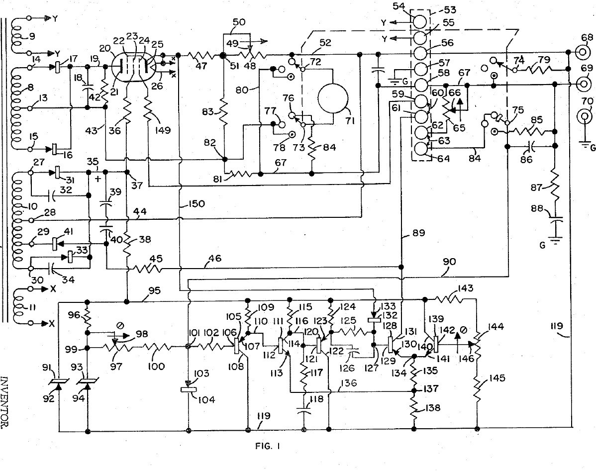


Bench Power Supply: Regulated, with Adjustable Current Limit and a Pentode Pass Tube (Gately, Forbro, US 3,243,690, 1966)
An adjustable bench supply that holds its output voltage steady and lets you set the most current it will deliver, so a circuit under test cannot be damaged. A pentode tube in series with the output is the regulator; a bridge with Zener references and a five-transistor amplifier keeps the output equal to the setting of one knob. A meter switch reads volts, amps, and the current limit, which can be set without disturbing the voltage.
Result: a regulated DC bench supply with adjustable current limiting.
Source: J. R. Gately (Forbro Design), US 3,243,690 (1966). Unknown: all component values and the output rating. Picture: the patent drawing.
උසස්
Unknown
උපදෙස්
1
1
Wire the mains side
Wire the mains side
In a case, wire the power cord through a switch and a fuse to the primary of a transformer with four secondaries, and put a neon lamp across the primary to show the supply is on. One secondary (6.3 V) goes to two terminals for outside use, one heats the pentode, one is the main supply and one the bias supply. Ours: the case. Not given: the other winding voltages.
මෙම පියවර සඳහා ද්රව්ය:
 ඇලුමිනියම් ආවරණ පෙට්ටිය1 case
 ප්ලග් සහිත නම්යශීලී රැහැන1 කැබැල්ල
 ටොගල් ස්විචය1 කැබැල්ල
 විලායකය1 කැබැල්ල
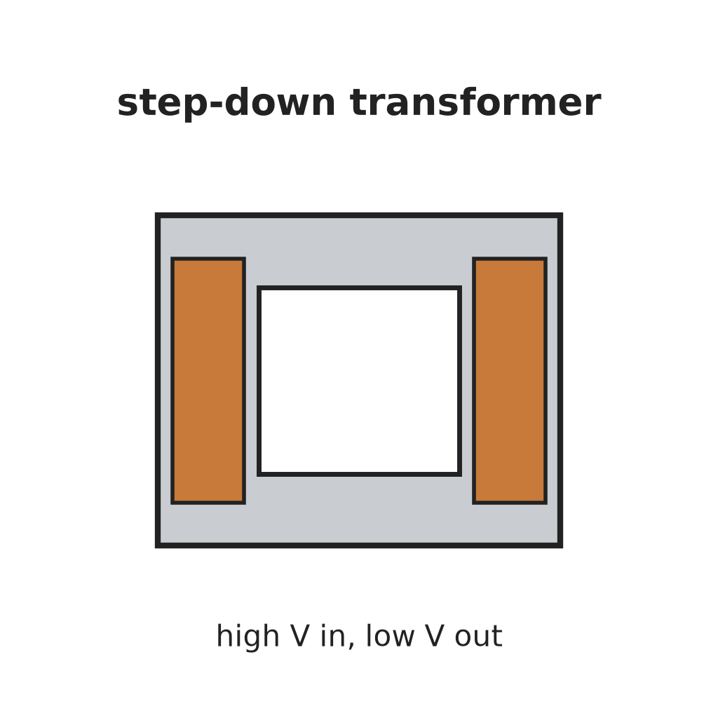 පියවර-අඩු ට්රාන්ස්ෆෝමරය1 four secondaries
 නියෝන් දර්ශක බුබුළ1 කැබැල්ල
 බයින්ඩිං පෝස්ට්2 6.3 V terminals
අවශ්ය මෙවලම්:
 අත් විදුම
 ඉස්කුරුප්පු නියන කට්ටලය
2
2
Build the rectifiers
Build the rectifiers
Rectify the centre-tapped main winding with two rectifiers and smooth it with a capacitor. From the bias winding make two more supplies: one through two rectifiers with by-pass capacitors to a smoothing capacitor, for the pentode's screen and the reference circuit; the other through one rectifier and a capacitor, for the pentode's grid bias. Not given: the values.
මෙම පියවර සඳහා ද්රව්ය:
 ඩයෝඩය5 rectifiers
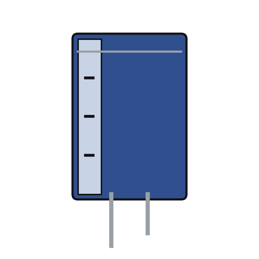 විද්යුත් විච්ඡේද ධාරිත්රකය3 smoothing
 ධාරිත්රක කට්ටලය1 by-pass
 පාස්සන ඊයම් කම්බිය1 as needed
අවශ්ය මෙවලම්:
 පෑස්සුම් කූරු
3
3
Fit the pass tube and reference
Fit the pass tube and reference
Put the pentode in series with the positive output: plate to the main supply, cathode through two current-sensing resistors (one fixed, one adjustable) to the + output terminal; suppressor tied to the cathode, screen fed through a resistor. Build the reference: a Zener fed through a resistor feeds a second Zener at constant current, giving a fixed voltage. Against it set two resistors and the voltage-control variable resistor: the output voltage is proportional to that resistor's setting. Not given: the tube type and values.
මෙම පියවර සඳහා ද්රව්ය:
 පෙන්ටෝඩ් නලය1 series pass tube
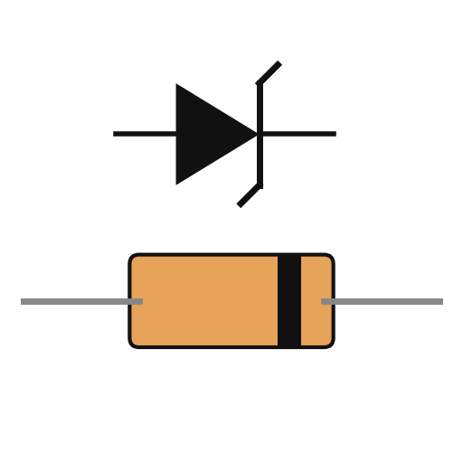 සීනර් දියෝඩය2 කැබලි
 ප්රතිරෝධය1 කට්ටලය
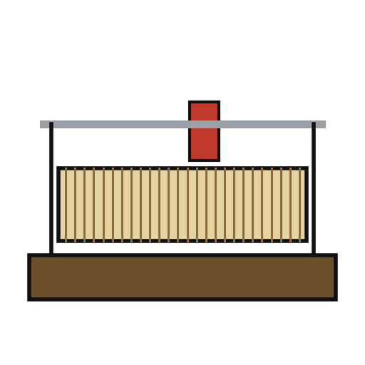 රියෝස්ටැටය2 voltage control, current-limit rangeබයින්ඩිං පෝස්ට්2 output + and -පාස්සන ඊයම් කම්බිය1 as needed
අවශ්ය මෙවලම්:
පෑස්සුම් කූරු4
4
Build the error amplifier and current limit
Build the error amplifier and current limit
Build a five-transistor amplifier that drives the pentode's grid to keep the bridge balanced: a PNP emitter follower, an NPN stage, a PNP emitter follower with a resistor-capacitor roll-off against oscillation, a PNP driver whose base resistor has a capacitor across it for quick response, and an NPN clamp whose base is set by a potentiometer. Feed the voltage across the current-sensing resistors to the driver's base through a diode: above the limit it takes over and turns the pentode down. Choose the fixed sensing resistor to limit at about 125 % of rated current, trim with the potentiometer, and use the adjustable one to set lower limits. Not given: the transistor types and values.
මෙම පියවර සඳහා ද්රව්ය:
 PNP ට්රාන්සිස්ටරය3 කැබලි
 NPN ට්රාන්සිස්ටරය2 කැබලිඩයෝඩය1 කැබැල්ල
 විභව මානය1 කැබැල්ලධාරිත්රක කට්ටලය1 roll-off, speed-upප්රතිරෝධය1 කට්ටලයපාස්සන ඊයම් කම්බිය1 as needed
අවශ්ය මෙවලම්:
පෑස්සුම් කූරු5
5
Fit the meter and use it
Fit the meter and use it
Fit a meter with a four-pole, three-position switch. Position 1 reads output volts through a multiplier resistor; position 2 reads current across a shunt in the negative line; position 3 (spring-return) puts a load resistor across the output and swaps a fixed resistor for the voltage control, so you can turn the limit control until the current limits at the value you want, without touching the voltage setting. Release the switch and use the supply.
මෙම පියවර සඳහා ද්රව්ය:
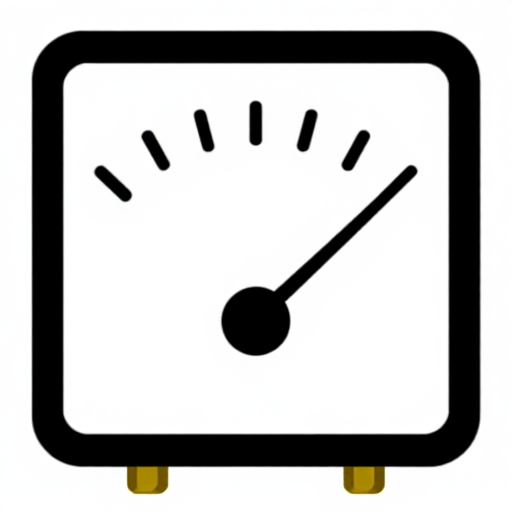 චලන දඟර පුවරු මීටරය1 කැබැල්ල
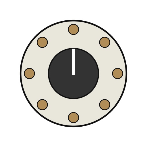 භ්රමණ ස්විචය1 4-pole, 3-positionප්රතිරෝධය1 multiplier, shunt, load resistors
 නොදන්නා ද්රව්යය1 terminal strip
අවශ්ය මෙවලම්:
පෑස්සුම් කූරුඉස්කුරුප්පු නියන කට්ටලයද්රව්ය
21- 1 caseස්ථානගත
- 1 කැබැල්ලස්ථානගත
- ස්ථානගත
- 1 කැබැල්ලස්ථානගත
- 1 four secondariesස්ථානගත
- 1 කැබැල්ලස්ථානගත
- ස්ථානගත
- 1 කැබැල්ලස්ථානගත
- 3 smoothingස්ථානගත
- 1 roll-off, speed-upස්ථානගත
- 3 as neededස්ථානගත
- 1 series pass tubeස්ථානගත
- 2 කැබලිස්ථානගත
- 1 multiplier, shunt, load resistorsස්ථානගත
- 2 voltage control, current-limit rangeස්ථානගත
- 3 කැබලිස්ථානගත
- 2 කැබලිස්ථානගත
- ස්ථානගත
- 1 කැබැල්ලස්ථානගත
- 1 4-pole, 3-positionස්ථානගත
- 1 terminal stripස්ථානගත
මෙම සැලසුම සාදන්නේ

CC0 පොදු වසම
මෙම බ්ලූප්රින්ට් CC0 යටතේ නිකුත් කර ඇත. ඔබට අවසර නොමැතිව පිටපත් කිරීම, වෙනස් කිරීම, බෙදා හැරීම සහ භාවිතා කිරීම කළ හැක.
බ්ලූප්රින්ට් හරහා නිෂ්පාදන මිලදී ගැනීමෙන් නිර්මාතෘට සහාය වන්න නිර්මාතෘ කොමිසම විකුණුම්කරුවන් විසින් නියම කළ, හෝ මෙම බ්ලූප්රින්ට්හි නව අනුවාදයක් සාදා ආදායම බෙදා ගැනීමට ඔබේ බ්ලූප්රින්ට්හි සම්බන්ධතාවයක් ලෙස ඇතුළත් කරන්න.