Creating 3D Models with Claude AI and Blender — From Conversation to .blend File
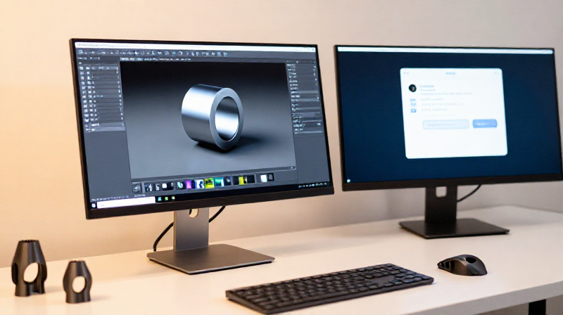
Blender is the most powerful free and open-source 3D modeling software in the world. Claude AI can write and execute Blender Python scripts to create precise 3D models — from simple shapes to complex parametric designs with engraved text, curved surfaces, and exact physical dimensions. This blueprint teaches you how to connect Claude to Blender and create publication-ready 3D design files through natural conversation.
Instead of learning Blender's complex UI with hundreds of hotkeys and menus, you describe what you want in plain language. Claude translates your description into Blender Python API calls — creating geometry, applying modifiers, cutting boolean operations, scaling to real-world dimensions, and exporting the finished file. The example model is a 1 kg cross-peen blacksmith hammer head with Elder Futhark runes engraved on both sides.
Two connection methods are covered: the Blender MCP server addon (for Claude Desktop with a live Blender viewport) and the headless Blender API (for Claude Code with server-side rendering). Both produce identical .blend files.
උපදෙස්
Install Blender
Install Blender
Download Blender from blender.org — it is free, open-source (GPL license), and runs on Windows, macOS, and Linux. Install version 4.0 or newer. Blender includes a full Python interpreter and a comprehensive Python API that allows every operation in the program to be scripted. This is what Claude uses to create 3D models — every button, menu, and tool in Blender has a Python equivalent.
After installation, open Blender once to confirm it launches. You will see the default startup scene with a cube, camera, and light. Close it — for the AI workflow, Blender will be controlled remotely.
Materials for this step:
 Blender (Software)1 piece
Tools needed:
 Desktop Computer
Choose your connection method
Choose your connection method
There are two ways to connect Claude to Blender. Choose the one that fits your setup:
Method A — Blender MCP Server (Claude Desktop): Install a Model Context Protocol (MCP) addon in Blender that turns it into a local server. Claude Desktop connects to it directly and can execute Python code, take screenshots of the viewport, and read scene information — all while you watch the model build in real time in the Blender window.
Method B — Headless Blender API (Claude Code): Run Blender in headless mode (no GUI) wrapped by a FastAPI server. Claude Code sends Python scripts via HTTP, Blender executes them and returns file outputs. This is faster for batch work and runs on a remote server, but you do not see the viewport live — you review the finished .blend file afterward.
Method A is better for interactive design where you want to see each change. Method B is better for automated pipelines, server-side generation, and working without a display.
Set up the Blender MCP Server (Method A)
Set up the Blender MCP Server (Method A)
Install the Blender MCP addon from GitHub (search for 'blender-mcp' — the addon provides an MCP-compatible server that runs inside Blender). In Blender: Edit → Preferences → Add-ons → Install from Disk → select the downloaded .zip. Enable the addon. A 'Blender MCP' panel appears in the sidebar (press N to toggle the sidebar, then select the MCP tab).
Click 'Start Server' in the MCP panel. Blender is now listening for connections from Claude. In Claude Desktop settings, add the Blender MCP server as a tool source (the addon documentation provides the configuration snippet). Once connected, Claude gains access to tools like execute_blender_code, get_scene_info, and get_viewport_screenshot — everything needed to design 3D models through conversation.
Materials for this step:
 Blender MCP Server Addon1 piece
Set up the headless Blender API (Method B)
Set up the headless Blender API (Method B)
Create a FastAPI server that wraps headless Blender. The server accepts Python scripts via a POST /execute endpoint, runs them in Blender's background mode (blender --background --python), and returns the output files. A minimal server needs just one endpoint:
Start Blender with: blender --background --python-expr "exec(script)" where script is the Python code received from Claude. Save the output files (.blend, .stl) to a job directory and serve them via a GET /files endpoint. Claude Code calls these HTTP endpoints to send scripts and retrieve the finished model files.
This is the same architecture used for AI image generation pipelines (ComfyUI) — a headless creative tool wrapped by an API, running on a server with GPU access.
Tools needed:
Desktop ComputerDescribe the model you want to create
Describe the model you want to create
Tell Claude what you want to build in plain language. Be specific about dimensions, materials, and physical properties. For example:
'Design a 1 kg cross-peen blacksmith hammer head. The striking face should be a rounded square, the peen should be horizontal (thin in Z, wide in Y) for pushing metal. Add Elder Futhark runes ᚦᛟᚱ (TOR) engraved 3 mm deep on both flat sides. Scale the geometry so the volume equals exactly 127.4 cm³ (1 kg of hardened steel at 7850 kg/m³ density). Include an oval eye hole for the handle.'
Claude will translate this description into a sequence of Blender Python operations. The more precise your description, the closer the first iteration will be to what you want. Use real measurements (millimeters, grams, degrees) rather than relative terms ('make it bigger').
Claude generates and executes Blender Python scripts
Claude generates and executes Blender Python scripts
Claude creates a Python script that uses the Blender Python API (bpy module) to build the model. A typical script sequence for the hammer head:
1. Create a cube primitive and scale it to the rough hammer dimensions
2. Subdivide the mesh to add geometry for shaping
3. Loop through vertices to sculpt the cross-peen taper, striking face profile, and center bulge
4. Apply a Subdivision Surface modifier for smooth curves
5. Cut the eye hole using a boolean DIFFERENCE operation with a cylinder
6. Calculate the mesh volume and apply a uniform scale factor to hit 1 kg of steel
7. Create small cube cutters for each rune stroke and boolean-subtract them from the surface
Claude sends this script to Blender (via MCP or API). Blender executes it and produces the 3D geometry. With MCP (Method A), you watch the model appear in the viewport in real time.
Review and iterate on the design
Review and iterate on the design
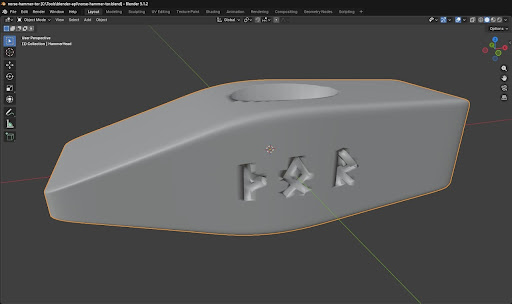
Inspect the model. With Method A, orbit around it in the Blender viewport. With Method B, download the .blend file and open it in Blender, or ask Claude to render a viewport screenshot. Check dimensions, proportions, and detail fidelity. Common issues on the first iteration and how to direct Claude to fix them:
• Text looks backwards on one side → specify which face (+Y or -Y) needs mirroring
• Model too small or too large → give the target dimension in mm
• Engravings disappeared on curved surface → Claude needs to query the actual surface position at each engraving location
• Boolean operations destroyed the mesh → tell Claude to use individual cutters per stroke, not joined geometry
• Features on wrong axis → always communicate using axis references (+X, -Y, +Z), never 'front' or 'back' which are ambiguous in 3D
Each fix is a conversation turn: describe the problem, Claude adjusts the script, re-executes, and you review again. Two to five iterations typically produces a finished model.
Verify the model from all angles
Verify the model from all angles
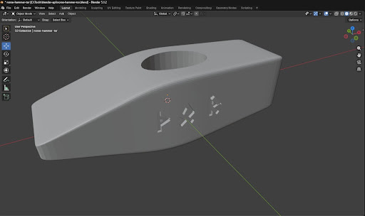
Rotate the model to check every face. Verify the rune engravings read correctly on both flat sides — text on the +Y face should mirror naturally when viewed from the +Y direction, and text on the -Y face should read correctly from the -Y direction. Check the eye hole is clean and centered. Confirm the cross-peen tapers smoothly without jagged edges.
In Blender, press Numpad 1 for front (-Y view), Ctrl+Numpad 1 for back (+Y view), Numpad 3 for right (+X view), and Numpad 7 for top (+Z view). These orthographic views reveal alignment issues that perspective view hides.
Save as .blend (primary format)
Save as .blend (primary format)
Save the model as a .blend file (File → Save As, or via script: bpy.ops.wm.save_as_mainfile(filepath='model.blend')). The .blend format is Blender's native format and the best choice for archival and sharing:
• Smallest file size — approximately 50% smaller than the equivalent STL (536 KB vs 1.2 MB for the hammer head)
• Preserves all modifier stacks, materials, scene settings, and edit history
• Fully editable — another maker can open it, change the rune text, resize for a different weight, or adjust any parameter
• Can be converted to any other format (STL, OBJ, glTF, 3MF) at any time via Blender or the Blender API
The .blend file is the single source of truth. All other formats are derived from it.
Export as .stl (universal 3D printing format)
Export as .stl (universal 3D printing format)
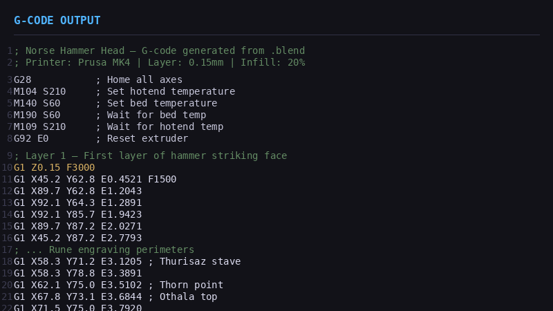
Export the model as STL for compatibility with 3D printers and slicer software (File → Export → STL, or via script: bpy.ops.wm.stl_export(filepath='model.stl')). STL is the universal format that every slicer (PrusaSlicer, Cura, BambuStudio) and every 3D printer accepts.
The STL file contains only the triangle mesh — no materials, no modifiers, no edit history. It is larger than the .blend (the mesh data is stored as plain text coordinates) and is not easily editable. Think of it as the 'compiled' output: good for printing, but you go back to the .blend source to make changes.
For best results, ensure all modifiers are applied before export (in the script, this is automatic). Check 'Selection Only' if your scene has multiple objects and you only want the hammer head.
Upload the design files to Youblob
Upload the design files to Youblob
When creating or editing a blueprint on Youblob, add a design step (content type: 'design') and upload the .blend file as the primary design file. The .stl can be uploaded as a second design step or as a supplementary download. Youblob's blueprint viewer will display an interactive 3D preview for STL files and a download button for .blend files.
Include the model dimensions, weight, and material density in the step description so other makers know the exact specifications. For parametric models (like this weight-scaled hammer), document which variables to change for customization — other makers should be able to modify the design for their needs without starting from scratch.
Best practices for AI-assisted 3D modeling
Best practices for AI-assisted 3D modeling
Lessons learned from designing the Norse hammer head and other models with Claude:
• Use axis references, not directions: Say '+Y face' and '-Z axis', never 'front' or 'top' — these are ambiguous in 3D and lead to mirrored results.
• Boolean operations need individual cutters: Joining multiple primitive shapes before a boolean creates non-manifold geometry. Keep each cutter as a separate object.
• Query the actual surface: After subdivision and modifiers, the mesh surface is not where the original dimensions suggest. Claude should measure vertex positions before placing engravings or cuts.
• Scale by volume, not dimensions: To hit a target weight, compute mesh volume using the signed tetrahedra method, then apply a uniform scale factor: (target_vol / current_vol) ^ (1/3).
• Iterate in 2-5 rounds: The first script gets 80% right. Each review-and-fix cycle catches remaining issues. Five iterations typically produces a production-ready model.
ද්රව්ය
2- 1 pieceස්ථානගත
- 1 pieceස්ථානගත
Connected Blueprint Materials
සම්බන්ධ බ්ලූප්රින්ට්
මෙම බ්ලූප්රින්ට් දැනුම බෙදා ගනී — ශිල්ප ක්රම, ද්රව්ය හෝ මූලධර්ම
Related blueprints
Other builds that share materials, tools, or techniques with this one.
CC0 පොදු වසම
මෙම බ්ලූප්රින්ට් CC0 යටතේ නිකුත් කර ඇත. ඔබට අවසර නොමැතිව පිටපත් කිරීම, වෙනස් කිරීම, බෙදා හැරීම සහ භාවිතා කිරීම කළ හැක.
බ්ලූප්රින්ට් හරහා නිෂ්පාදන මිලදී ගැනීමෙන් නිර්මාතෘට සහාය වන්න නිර්මාතෘ කොමිසම විකුණුම්කරුවන් විසින් නියම කළ, හෝ මෙම බ්ලූප්රින්ට්හි නව අනුවාදයක් සාදා ආදායම බෙදා ගැනීමට ඔබේ බ්ලූප්රින්ට්හි සම්බන්ධතාවයක් ලෙස ඇතුළත් කරන්න.