කලාව
රූපලාවණ්ය සහ සුවතාව
ශිල්පය
සංස්කෘතිය සහ ඉතිහාසය
විනෝදාස්වාදය
පරිසරය
ආහාර සහ පාන
ප්රතිලෝම ඉංජිනේරු
විද්යාවන්
ක්රීඩා
තාක්ෂණය
පැළඳිය හැකි
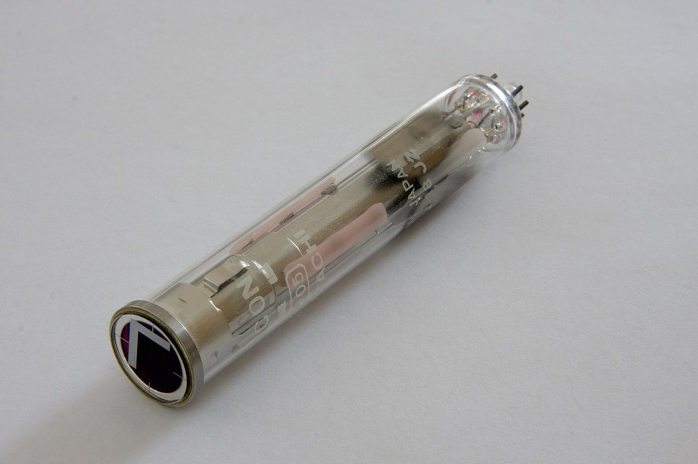


The Vidicon Camera Tube
A cathode ray tube turns a signal into a picture. Run the same idea backwards and you have the harder half of television: turn a picture into a signal, live, thirty times a second, with no film and no delay.
RCA's Paul Weimer, Stanley Forgue and Robert Goodrich published the vidicon in 1950, and it is the design that made television cameras ordinary. What came before it was enormous. Zworykin's iconoscope of 1931 needed light levels that made studios unbearable to work in. The image orthicon of 1945 was superb and was the size of a rolled-up newspaper, cost as much as a car, and needed a skilled operator riding its controls.
The vidicon is a tube 25 mm across and 130 mm long with one simple idea inside it: a sheet of photoconductor — exactly the material from the first blueprint in this batch — with a transparent conductive film on the front and nothing at all on the back. Light lands on the front and makes the photoconductor locally conductive, so charge leaks off the back surface in proportion to the light. Then an electron beam scans the back surface and puts the charge back. The current it takes to do that, moment by moment, IS the video signal.
It is beautifully economical. The target integrates light for a whole frame between visits from the beam, so it collects everything rather than sampling; the scan reads and resets in the same operation; and the whole thing runs on a few hundred volts instead of the image orthicon's complexity.
And it inherits, directly and unavoidably, the two defects measured in the photocell blueprint. The photoconductor is slow, so a moving object smears — the fault everybody who used one called LAG. And a bright static image sits on the target long after it has gone, which is burn-in, and it is why every early television camera operator was taught never to point the camera at a light.
The sibling blueprint at the end of this batch is the CCD, which solved both by abandoning photoconductive gain entirely. This one is the device it had to beat.
උසස්
5 hours
උපදෙස්
1
1
The target: a capacitor that light discharges
The target: a capacitor that light discharges
Take the whole tube apart in your head into four parts, front to back.
THE FACEPLATE is glass with a transparent conductive coating on its inner surface — tin oxide, the same material that is on the inside of a shop window heater and on the LCD glass later in this batch. It is called the signal plate and it is the tube's output terminal. It is transparent so light gets through it and conductive so charge can be collected from it.
THE TARGET is a layer of photoconductor evaporated onto the signal plate, a few micrometres thick. In the original vidicon this was antimony trisulfide. It is a semiconductor with a bandgap around 1.7 eV, which puts its response across the visible spectrum, and in the dark it is a very good insulator.
THE SCANNED FACE is the back of the target, and there is nothing on it. It is bare photoconductor facing into the vacuum.
THE GUN is at the far end, with a deflection yoke and a focus coil round the tube, exactly as in the cathode ray tube blueprint this one links back to.
NOW THE MECHANISM, and it is worth going slowly because it is not what people assume.
The target is a capacitor. The signal plate is one plate; the free back surface is the other; the photoconductor is the dielectric between them, a few micrometres thick, which makes the capacitance per unit area large.
START WITH THE BEAM having just scanned a spot. The beam is a source of electrons at essentially zero volts, so it charges that patch of the back surface down to cathode potential and then stops — it cannot push it more negative than its own source. The signal plate is held at maybe +30 V. So every patch of the target is now a small charged capacitor with about 30 V across its few micrometres.
NOW LEAVE IT for one frame time, one fortieth of a second in a 25 Hz system.
IN THE DARK, the photoconductor is an insulator and the charge stays. The patch is still at cathode potential when the beam comes round again, so the beam has nothing to do and no current flows. Dark equals no signal.
IN THE LIGHT, the photoconductor conducts in proportion to the illumination, so charge leaks through it from the back surface to the signal plate. That patch of back surface drifts positive. How far positive depends on how much light fell there and for how long — it INTEGRATES.
WHEN THE BEAM RETURNS it must put back exactly the charge that leaked away, to pull that patch back down to cathode potential. That replacement charge, flowing through the signal plate to the external circuit, is the video signal.
Three things follow immediately and each one matters.
IT INTEGRATES, so it is far more sensitive than a device that only samples the light at the instant the beam passes. The whole frame time is exposure time. This is the same reason a photographic plate beats an eye at astronomy.
THE SIGNAL IS A CURRENT INTO A CAPACITOR, so the tube's output impedance is high and awkward and the preamplifier that follows it determines the noise floor of the entire camera. Camera tube preamplifiers were an art in themselves.
AND THE BEAM RESETS AS IT READS. There is no separate erase. Reading and clearing are the same operation, which is elegant and also means you get exactly one look at each frame.
අවශ්ය මෙවලම්:
 විඩිකෝන් කැමරා නලය (පැරණි උපකරණයකින් ලබාගත්)
2
2
Where an image goes on its way to being a signal
Where an image goes on its way to being a signal
The diagram traces one point of light from the lens to the video output, and marks at each stage what is gained and what is irretrievably lost.
The reason to draw it rather than describe it is that three of these stages are shared with every image sensor ever built and two of them are peculiar to the tube. Being able to see which is which is what makes the CCD blueprint at the end of the batch legible: the CCD keeps the shared stages, throws away the two peculiar ones, and adds two problems of its own.
FOLLOW THE LOSSES. Photons that miss the target are gone. Photons absorbed outside the photoconductor's response band are gone. Charge that has not fully leaked away by the time the beam arrives is lag. Charge that leaked away from a NEIGHBOURING patch is resolution loss. And the beam's own landing spot has a finite size, which sets the tube's resolution independently of everything else.
The stage marked BEAM LANDING is where tube cameras differ most from anything modern. There are no pixels in a vidicon. The target is continuous, and the picture is divided up only by where the beam happens to be at each moment and how sharply it is focused. Resolution is therefore a property of the SCANNING, not of the sensor, and it degrades at the edges of the picture where the beam lands obliquely and its spot becomes an ellipse.
That single fact is why tube cameras needed constant adjustment and why two cameras never quite matched, and it is the deepest reason the industry eventually wanted something with a fixed physical grid.
Flow
Loading...
අවශ්ය මෙවලම්:
 මේස පරිගණකය
3
3
Lag: put a number on the smear
Lag: put a number on the smear
Jupyter සටහන් පොත පූරණය වෙමින්…
අවශ්ය මෙවලම්:
මේස පරිගණකයඅවශ්ය මෙවලම්
2- ස්ථානගත
සම්බන්ධ බ්ලූප්රින්ට්
මෙම බ්ලූප්රින්ට් දැනුම බෙදා ගනී — ශිල්ප ක්රම, ද්රව්ය හෝ මූලධර්ම

CC0 පොදු වසම
මෙම බ්ලූප්රින්ට් CC0 යටතේ නිකුත් කර ඇත. ඔබට අවසර නොමැතිව පිටපත් කිරීම, වෙනස් කිරීම, බෙදා හැරීම සහ භාවිතා කිරීම කළ හැක.
බ්ලූප්රින්ට් හරහා නිෂ්පාදන මිලදී ගැනීමෙන් නිර්මාතෘට සහාය වන්න නිර්මාතෘ කොමිසම විකුණුම්කරුවන් විසින් නියම කළ, හෝ මෙම බ්ලූප්රින්ට්හි නව අනුවාදයක් සාදා ආදායම බෙදා ගැනීමට ඔබේ බ්ලූප්රින්ට්හි සම්බන්ධතාවයක් ලෙස ඇතුළත් කරන්න.