

Plain Bearing with Oil Groove
ညွှန်ကြားချက်များ
Make a split bearing shell with clearance
Make a split bearing shell with clearance
The clearance is not slop — it is the space the oil wedge lives in.
- Make two half shells from brass or bronze bar to fit a 25 mm shaft.
- Bore them, assembled, to 25.05 mm — roughly one thousandth of the diameter as clearance.
- Scrape or file the bore until a marker transfer shows even contact.
- Mount in a split plywood housing bolted with M6 × 50 hex bolts × 4, M6 flat washers × 8 and M6 hex nuts × 4.
Clearance of about 0.001 times the diameter is the classic rule. Too tight and no wedge can form, so it runs hot and seizes. Too loose and the film is thick, the pressure low, and the shaft wanders. This one dimension is the difference between a bearing and a bushing that is about to fail.
Bore the shells assembled, not separately, or the two halves will not form one circle when bolted together.ဤအဆင့်အတွက် ကုန်ကြမ်းများ:
 ကြေးဝါ တုံးလုံး1 ခု
 သစ်သားအလွှာပြား1 ရွက်
 ပြားချပ်ချပ်ဝါရှာ8 ခု
 ခြောက်ထောင့်နတ်4 ခု
လိုအပ်သော ကိရိယာများ:
 ကြိုးမဲ့ တူးစက်
 တူးစက်ခေါင်းအစုံ
 ရိုက်တံအစုံ
 စားပွဲညှပ်
 ဒစ်ဂျစ်တယ် ကာလီပါ ၆ လက်မ
 ခြောက်ထောင့်သော့အစုံ
Establish where the load actually acts
Establish where the load actually acts
You cannot place a groove correctly without knowing this.
- Mount the bearing and hang the working load from the shaft.
- Mark the housing at the point where the shaft is pressed hardest into the shell — usually directly below a hanging load.
- Blue the shaft and turn it slowly; the wiped band shows the loaded arc.
- Mark that arc on the shell and label it clearly.
This is the step people skip, and it decides everything that follows. The loaded zone is where the film pressure builds, and it must remain a continuous unbroken surface. Every subsequent decision about grooves, feed holes and reliefs is made relative to this arc, so mark it permanently on the shell.
If the load direction can change — a belt drive that runs both ways, or a machine with reversing loads — then there is no permanently unloaded zone, and grooving must be reconsidered entirely. That is a real design constraint, not a detail.လိုအပ်သော ကိရိယာများ:
 ပေါင်းစပ်ထောင့်တိုင်း
 အလယ်ဗဟိုအမှတ်ထိုးတံဒစ်ဂျစ်တယ် ကာလီပါ ၆ လက်မ
Cut the groove in the UNLOADED half
Cut the groove in the UNLOADED half
Distribution above, pressure below.
- In the unloaded shell half, cut an axial groove about 4 mm wide and 2 mm deep, running most of the shell's length.
- Stop the groove about 5 mm short of each end so oil is not simply dumped out of the sides.
- Drill the oil feed hole into the middle of that groove.
- Round and blend the groove edges smoothly into the bore.
Two details that look cosmetic and are not. Stopping short of the ends keeps oil in the bearing instead of letting it run straight out. Blending the edges lets the shaft sweep oil smoothly out of the groove and into the converging gap — a sharp edge scrapes the film off the shaft instead, which is the opposite of what is wanted.
Cut the groove in the unloaded half only. In a moment you will cut one in the loaded half on a second shell, and compare — but do that as a deliberate experiment, not by accident.ဤအဆင့်အတွက် ကုန်ကြမ်းများ:
ကြေးဝါ တုံးလုံး1 ခုလိုအပ်သော ကိရိယာများ:
ရိုက်တံအစုံကြိုးမဲ့ တူးစက်တူးစက်ခေါင်းအစုံစားပွဲညှပ်ဒစ်ဂျစ်တယ် ကာလီပါ ၆ လက်မGroove the loaded half on a second shell and compare
Groove the loaded half on a second shell and compare
Prove the rule instead of memorising it.
- Make a second shell identical to the first, but cut the groove in the LOADED half.
- Run each in turn under the same load, speed and oil feed for the same time.
- Measure temperature rise for each.
- Measure the torque needed to turn the shaft in each.
- Inspect both bores afterwards for polishing or scoring.
ဤအဆင့်အတွက် ကုန်ကြမ်းများ:
ကြေးဝါ တုံးလုံး1 ခုလိုအပ်သော ကိရိယာများ:
ကြိုးမဲ့ တူးစက် အချိန်တိုင်းနာရီရိုက်တံအစုံဒစ်ဂျစ်တယ် ကာလီပါ ၆ လက်မ
The film that carries the load, and history
The film that carries the load, and history
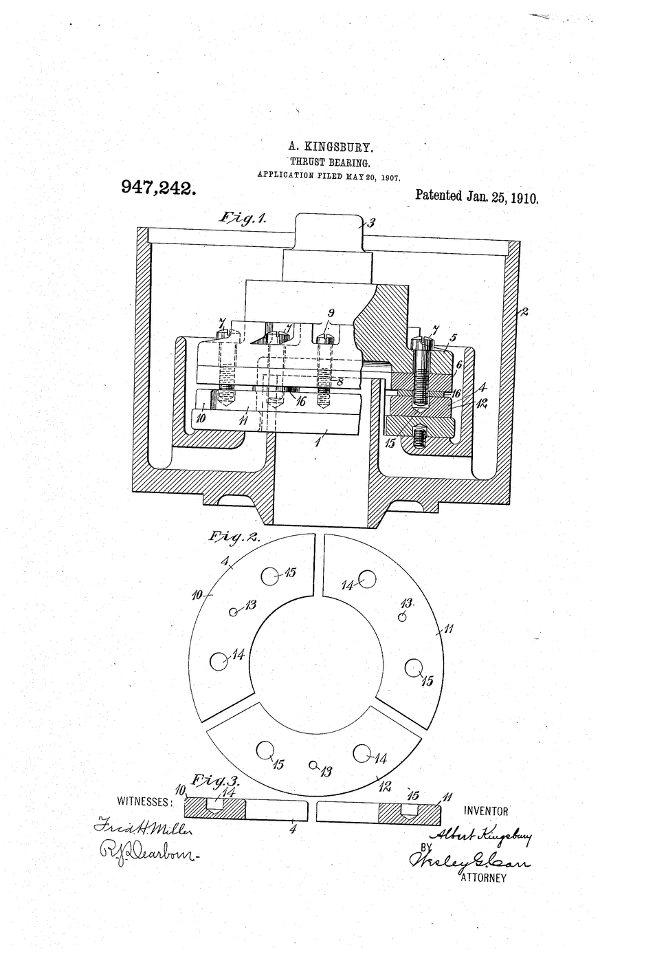
Beauchamp Tower discovered the pressure in an oil film by accident in the 1880s while testing railway axle bearings for the Institution of Mechanical Engineers: an oil hole he had drilled kept pushing its plug out, and the plug was being ejected by the film's own pressure. Osborne Reynolds took Tower's measurements and produced the theory in 1886 — the equation that still bears his name and still governs bearing design.
What the theory says, in plain terms: the rotating shaft drags oil into a gap that narrows, and because the oil cannot escape fast enough it is pressurised, and that pressure lifts the shaft clear. Once running, the surfaces never touch. This is why a plain bearing can carry enormous loads for decades with no measurable wear — and also why the dangerous moments are starting and stopping, when the film has not yet formed. Most plain bearing wear happens in the first seconds of each start.
Against the rolling bearings elsewhere in this catalogue: a ball or roller bearing works immediately at any speed, needs less oil and tolerates neglect, but has a fatigue life and eventually fails no matter how well treated. A plain bearing needs speed and oil supply to work at all, and in exchange can last essentially forever, run quieter and carry higher loads in less space. It is why large engines and turbines still use plain bearings on their main shafts.
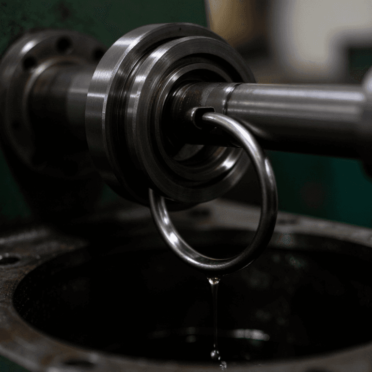
The whole batch converges here. Every feeder — wick, drip, grease, oil ring — exists to keep this film supplied. And the seals in part one exist to keep that same oil from escaping and dirt from spoiling it. Sealing and lubrication are one subject, and the film is what they are both for.
ပစ္စည်းများ
4- 1 ခုနေရာယူပစ္စည်း
- 1 ရွက်နေရာယူပစ္စည်း
- နေရာယူပစ္စည်း
- 4 ခုနေရာယူပစ္စည်း
လိုအပ်သော ကိရိယာများ
9- 1 vendor sell this, none ship to you yetနေရာယူပစ္စည်း
- နေရာယူပစ္စည်း
- နေရာယူပစ္စည်း
- နေရာယူပစ္စည်း
- နေရာယူပစ္စည်း
- နေရာယူပစ္စည်း
- နေရာယူပစ္စည်း
- နေရာယူပစ္စည်း
- နေရာယူပစ္စည်း
ဆက်စပ် အစီအစဉ်များ
ဤအစီအစဉ်များသည် အသိပညာမျှဝေသည် — နည်းပညာ၊ ပစ္စည်း သို့မဟုတ် မူများ

CC0 အများပိုင်
ဤအစီအစဉ်ကို CC0 အောက်တွင် ထုတ်ဝေထားသည်။ ခွင့်ပြုချက်မလိုဘဲ ကူးယူ၊ ပြင်ဆင်၊ ဖြန့်ဝေ နှင့် အသုံးပြုနိုင်သည်။
အစီအစဉ်မှတစ်ဆင့် ကုန်ပစ္စည်းများဝယ်ယူ၍ လက်မှုပညာရှင်ကို ပံ့ပိုးပါ လက်မှုပညာရှင် ကော်မရှင် ရောင်းချသူက သတ်မှတ်သည်၊ သို့မဟုတ် ဤအစီအစဉ်၏ ဗားရှင်းအသစ်ဖန်တီး၍ ဝင်ငွေခွဲဝေရန် သင့်အစီအစဉ်တွင် ချိတ်ဆက်မှုအဖြစ် ထည့်သွင်းပါ။