УРЛАГ
ГОО САЙХАН БА ЭРҮҮЛ МЭНД
ГАРААР ХИЙСЭН
СОЁЛ БА ТҮҮХ
ҮЗВЭР НААДАМ
БАЙГАЛЬ ОРЧИН
ХООЛ БА УНДАА
УРВУУ ИНЖЕНЕРЧЛЭЛ
ШИНЖЛЭХ УХААН
СПОРТ
ТЕХНОЛОГИ
ӨМСДӨГ ХЭРЭГСЭЛ
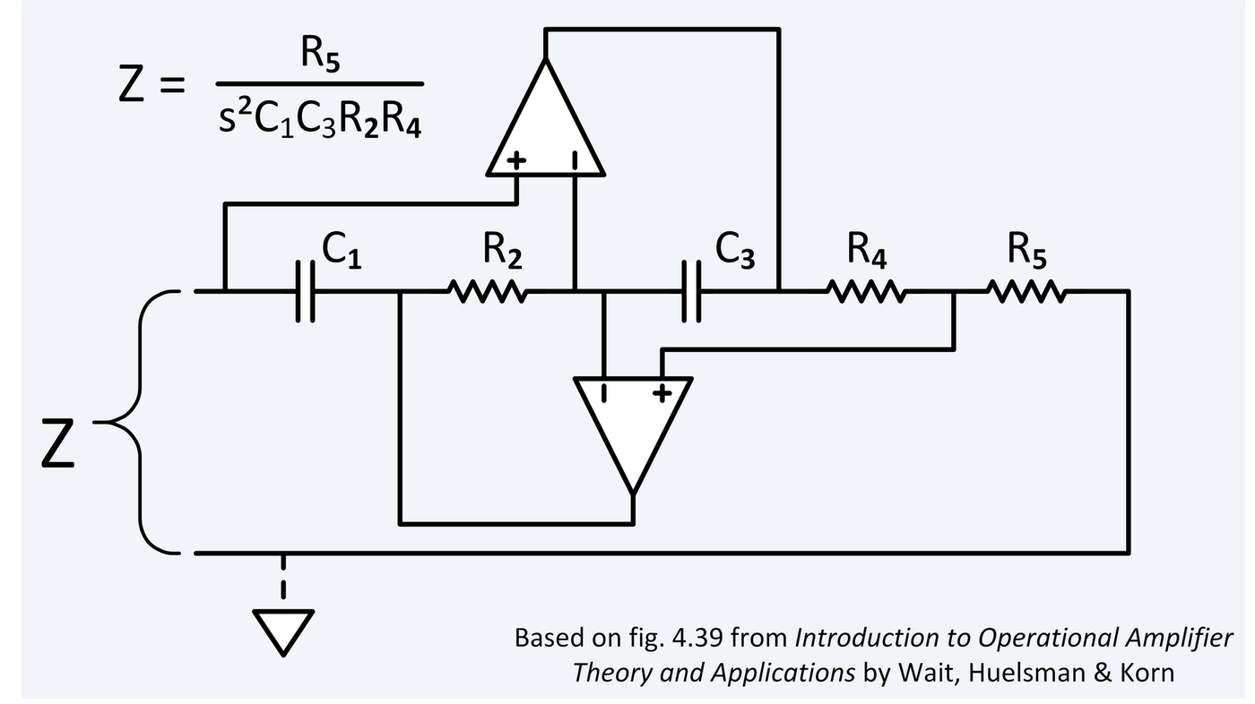


Reading a Schematic: It Shows Connections, Not Layout
A schematic is not a picture of the circuit. It says nothing about where parts sit, how long the wires are, or what the thing looks like — and beginners lose a lot of time trying to read it as a map.
What it does say, exactly and completely, is WHAT IS CONNECTED TO WHAT. A line is not a wire; it is a statement that these points are the same electrical node. Understanding that one substitution makes every schematic readable.
It is also the format every datasheet, every repair guide and every published circuit here uses, so it is the reading skill that unlocks the rest of the catalogue.
Анхан шат
3 hours
Зааварчилгаа
1
1
Lines are nodes, and a dot means joined
Lines are nodes, and a dot means joined
Trace one line from end to end and mark every component that touches it. That whole line, however it bends, is ONE electrical point — a node.
Where two lines cross with a DOT they are connected; without a dot they simply pass over each other and are unrelated. Modern schematics avoid the ambiguity by never crossing connected lines at all, but older drawings use a little hop over the crossing instead, and both conventions appear in the published blueprints here.
Physical length is meaningless. A line an inch long and one that runs across the page say exactly the same thing, which is why a schematic and the board built from it look nothing alike.
2
2
Power at the top, ground at the bottom, signal left to right
Power at the top, ground at the bottom, signal left to right
Once you know the convention, most schematics are readable at a glance: positive supply along the top, ground along the bottom, and the signal flowing from input on the left to output on the right.
Supplies are often drawn as short stubs labelled +5V or VCC rather than lines running across the page, and every ground symbol on the sheet is the same node even though they are not joined by any drawn line. That is the commonest confusion after the dot: a dozen separate ground symbols are one connection.
Named labels work the same way. Two stubs both labelled SDA are connected, wherever they are on the sheet, and that is how a large circuit fits on a page without becoming a plate of spaghetti.
3
3
Build one from the drawing, on a breadboard
Build one from the drawing, on a breadboard
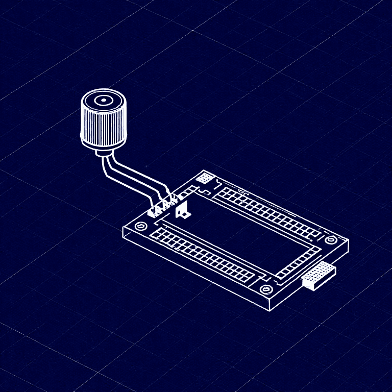
Take a simple published circuit — an LED and its resistor, or the potentiometer of SIK Circuit 2 — and build it from the schematic alone, without looking at any photograph of the finished thing.
Work node by node rather than component by component. Pick a node on the drawing, find every leg that belongs to it, and put them all in one breadboard row. Then the next node. Building node-by-node is almost mechanical; building component-by-component means constantly re-checking where the last leg went.
When it works, compare your layout to someone else's build of the same schematic. They will look completely different and both be correct, which is the point of the whole format.
Энэ алхмын материал:
 LED иж бүрдэл1 ширхэг
 Эсэргүүцлийн иж бүрдэл1 ширхэг
Шаардлагатай багаж:
 Макет самбар
 Холбогч утас
 Мультиметр
4
4
The symbols worth knowing on sight
The symbols worth knowing on sight
A small set covers most circuits. Resistor: a zigzag, or a plain rectangle in the international style — both mean the same thing and you will meet both. Capacitor: two parallel lines, and if one is curved it is POLARISED and must go in the right way round. Diode: a triangle pointing at a bar, and conventional current flows the way the triangle points. An LED is that with two arrows leaving it.
Transistor: a circle with three legs, one of which carries an arrow. The arrow is on the emitter and its direction tells you NPN from PNP — pointing out is NPN. Ground: a stack of shrinking horizontal lines.
Learn these eight and you can read most of the published circuits here without looking anything up. The rest you meet as you need them.
5
5
Annotate the drawing with the voltages you expect
Annotate the drawing with the voltages you expect
Before you power anything, write on the schematic what you think the voltage at each node should be. Supply rails, the junction of a divider, either side of an LED.
Now the schematic is a test plan. When it does not work you put the black probe on ground and walk the red probe along the drawing, comparing every node against the number you wrote. The first place reality disagrees with your annotation is where the fault lives.
This habit is what turns a schematic from a construction diagram into a diagnostic instrument, and it is exactly the method the fault-finding rung formalises.
Шаардлагатай багаж:
Мультиметр Тооны машин
Материал
2- 1 ширхэгТүр орлуулагч
- -с эхэлж$5.64
Шаардлагатай багаж
4- Макет самбар10% комиссMagento Legacy Storeships internationallyТүр орлуулагч
- Холбогч утас10% комиссMagento Legacy Storeships internationallyТүр орлуулагч
- Түр орлуулагч
- Түр орлуулагч
Холбоотой загварууд
Эдгээр загварууд мэдлэг хуваалцдаг — арга техник, материал эсвэл зарчим

CC0 Нийтийн домэйн
Энэ загвар CC0 дор гаргагдсан. Та зөвшөөрөл авахгүйгээр хуулах, өөрчлөх, түгээх, ашиглах боломжтой.
Загвараар дамжуулан бүтээгдэхүүн худалдаж авч Бүтээгчийг дэмжээрэй Бүтээгчийн шимтгэл Борлуулагчаар тогтоосон, эсвэл энэ загварын шинэ хувилбар үүсгэж орлогоо хуваахын тулд өөрийн загварт холбоос болгон оруулна уу.