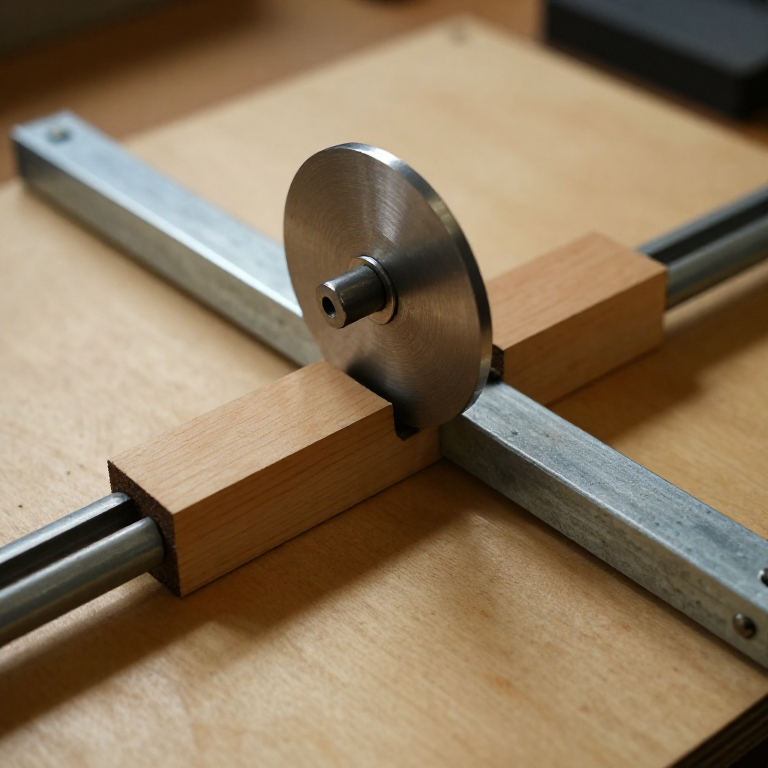


Scotch Yoke
Зааварчилгаа
Cut the baseplate and mark the centreline
Cut the baseplate and mark the centreline
Everything else is located from one line, so this line decides whether the model runs or binds.
- Cut a baseplate 300 × 150 mm from 18 mm Baltic birch plywood.
- Scribe a centreline down the 300 mm length with the combination square.
- Mark the crank centre 90 mm from the left end, on the centreline.
- Centre-punch that point.
Modern build spec (derived). 18 mm ply is chosen because it takes an M5 thread insert or a through-bolt without splitting, and it stays flat. A cast iron bed does the same job in the original machines; here rigidity comes from thickness.
Punch every hole centre before drilling. A drill bit started on unpunched plywood wanders across the grain, and a crank centre 1 mm out of place shows up as a visible wobble over the 80 mm stroke.Энэ алхмын материал:
 Балтийн хусан фанер1 хуудас
Шаардлагатай багаж:
 Хөрөө (лобзик)
 Хосолсон өнцөг хэмжигч
 Төвлүүлэх цүүц
 Дижитал штангенциркуль 6 инч
Make the crank disc and fit the pin
Make the crank disc and fit the pin
The crank throw sets the stroke exactly — stroke is twice the throw, with no approximation.
- Cut a 100 mm disc from 6 mm aluminium flat bar stock, or from 18 mm ply if working in wood only.
- Drill the centre 8.0 mm for the main shaft.
- Mark the pin centre 40 mm from the disc centre and drill 5.0 mm.
- Fit an M5 × 30 socket head cap screw as the crank pin, secured behind the disc with an M5 flat washer and M5 hex nut.
- Slip a 608 bearing (8 mm bore, 22 mm OD) over a stepped bush on the pin so the bearing outer race is what contacts the slot.
What the patent-era machines used: a hardened steel pin running directly in a bronze-lined slot, oiled by hand. Modern build spec (derived): a 608 sealed bearing on an M5 pin — the same job, no oiling, and it converts sliding contact into rolling contact at the one place this mechanism wears fastest.
Check the throw with the caliper before assembly: measure centre-to-centre, not edge-to-edge. A 1 mm error here becomes a 2 mm stroke error.Энэ алхмын материал:
 Хавтгай хөнгөн цагаан баганз1 ширхэг
 Хавтгай угаагуур2 ширхэг
 Зургаан талт эрэг2 ширхэг
 Бөмбөлөгт холхивч1 ширхэг
Шаардлагатай багаж:
 Утасгүй өрөм
 Өрмийн үзүүрийн иж бүрдэл
 Төмөр хөрөөний хүрээ ба ир
 Ширээний хавчаар
 Гилбэрийн иж бүрдэл
 Зургаан талт түлхүүрийн иж бүрдэл
Cut the yoke slot to the bearing, not to a number
Cut the yoke slot to the bearing, not to a number
The slot width is the single fit that decides whether it runs sweetly or rattles.
- Cut the yoke 180 × 60 mm from 18 mm ply.
- Measure your bearing's actual outer diameter with the caliper — a 608 is nominally 22 mm but measure it.
- Mark a slot across the yoke's width, 100 mm long, at the measured OD plus 0.2 mm.
- Drill a 20 mm hole at each end of the slot, then join the holes with the coping saw.
- File the two long faces straight and parallel, testing with the bearing as you go.
Энэ алхмын материал:
Балтийн хусан фанер1 хуудасШаардлагатай багаж:
 Муруй хөрөөӨрмийн үзүүрийн иж бүрдэлГилбэрийн иж бүрдэлДижитал штангенциркуль 6 инчШирээний хавчаар
Build the guides and set the assembly order
Build the guides and set the assembly order
Order matters here — get it wrong and you cannot reach a fastener.
- Cut two guide rails 200 × 25 mm from 6 mm aluminium flat bar.
- Clamp both rails to the baseplate in their final positions and drill through rail and base together, 4.2 mm, four holes per rail.
- Countersink the underside of the baseplate.
- Fit the crank disc and its bearing FIRST, then slide the yoke into place, then fit the second guide rail.
- Fix each rail with M4 × 25 socket head cap screws × 8, M4 flat washers × 16 and M4 nylon insert lock nuts × 8.
- Set the running clearance by slipping a sheet of paper between yoke and rail before final tightening, then withdraw it.
Why lock nuts: this mechanism reverses direction twice per revolution, and every reversal is a shock load through the guides. Plain nuts walk loose within minutes of running; nylon insert lock nuts do not. That is a specification decision, not a preference.
Drilling rail and base together is what guarantees the two rails end up parallel. Marking and drilling them separately accumulates error and the yoke will bind at one end of its travel.Энэ алхмын материал:
Хавтгай хөнгөн цагаан баганз1 ширхэг Дотор зургаан талт толгойтой шураг8 ширхэгХавтгай угаагуур16 ширхэг
 Нейлон оруулгатай тогтоох гайка8 ширхэг
Шаардлагатай багаж:
Утасгүй өрөмӨрмийн үзүүрийн иж бүрдэл Хонхорлогч өрмийн иж бүрдэлЗургаан талт түлхүүрийн иж бүрдэлХосолсон өнцөг хэмжигч
Measure the motion, and history
Measure the motion, and history
Prove the sine wave before reading further.
- Mark the crank rim every 30 degrees.
- Turn the crank one increment at a time and measure the yoke position with the caliper at each.
- Plot position against angle — you get a clean sinusoid.
- Now compute the same plot for a crank and connecting rod of equal throw and compare.
The connecting rod's curve is NOT a sine — it is skewed, because the rod's angularity makes the piston move faster on one half of the stroke than the other. That skew is the second harmonic that engine balancing has to deal with. The Scotch yoke has none of it, which is its genuine advantage.
History. The mechanism is old and its name is disputed; it appears in 19th century machine practice and is documented in the standard mechanism catalogues of the period, including Brown's Five Hundred and Seven Mechanical Movements of 1868. It has been applied in steam pumps, in the Bourke engine, in some radial engines and widely in test rigs where a true sinusoidal motion is required.
The honest limit, which is why it is not in your car. The pin slides along the slot as it rotates, and the sliding velocity is highest exactly where side force is greatest. In a high-speed engine that means unacceptable wear at the slot faces, and lubricating a reciprocating slot is much harder than lubricating a rotating bearing. The connecting rod wins in engines not because its motion is better but because it wears far less. This build sidesteps most of that with a rolling bearing — a modern option the original had no access to, and precisely the kind of substitution worth recording.
Where it sits among its siblings: the Geneva drive converts rotation into intermittent rotation; the Scotch yoke converts rotation into pure reciprocation; a crank and rod does the same job with less wear and a distorted waveform. Three answers, three different costs.
Шаардлагатай багаж:
Дижитал штангенциркуль 6 инчМатериал
8- 1 хуудасТүр орлуулагч
- 1 ширхэгТүр орлуулагч
- 2 ширхэгТүр орлуулагч
- 2 ширхэгТүр орлуулагч
- Түр орлуулагч
- Түр орлуулагч
- 16 ширхэгТүр орлуулагч
- 8 ширхэгТүр орлуулагч
Шаардлагатай багаж
12- 1 vendor sell this, none ship to you yetТүр орлуулагч
- Түр орлуулагч
- Түр орлуулагч
- Түр орлуулагч
- 1 vendor sell this, none ship to you yetТүр орлуулагч
- Түр орлуулагч
- Түр орлуулагч
- Түр орлуулагч
- Түр орлуулагч
- Түр орлуулагч
- Түр орлуулагч
- Түр орлуулагч
Холбоотой загварууд
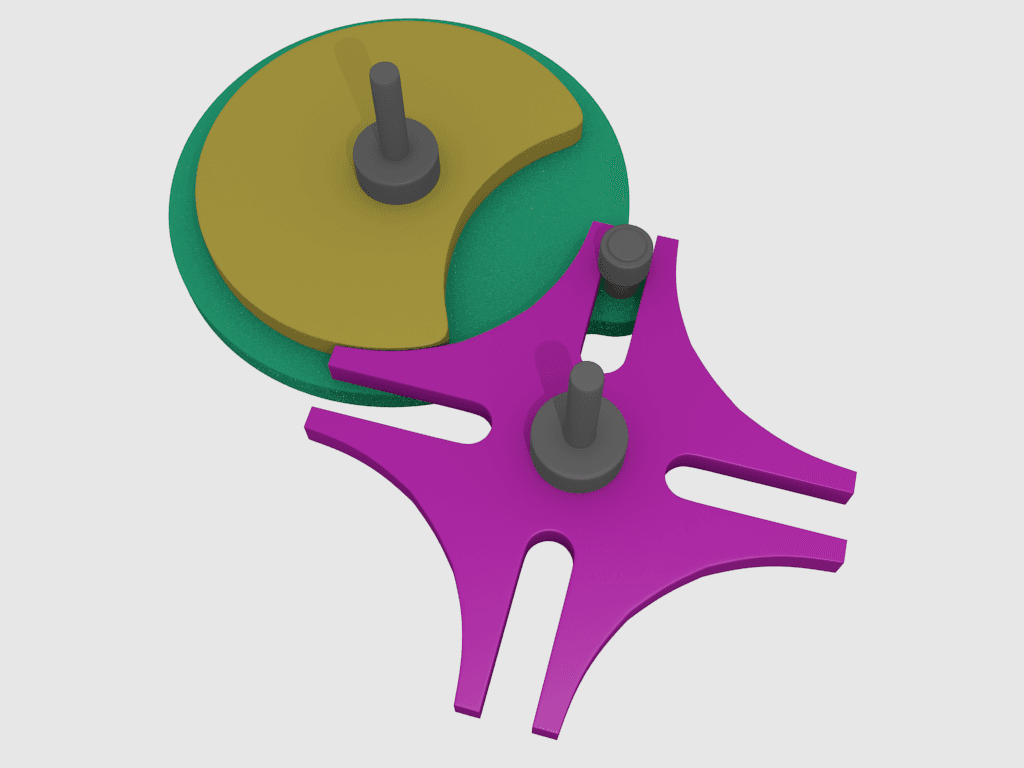
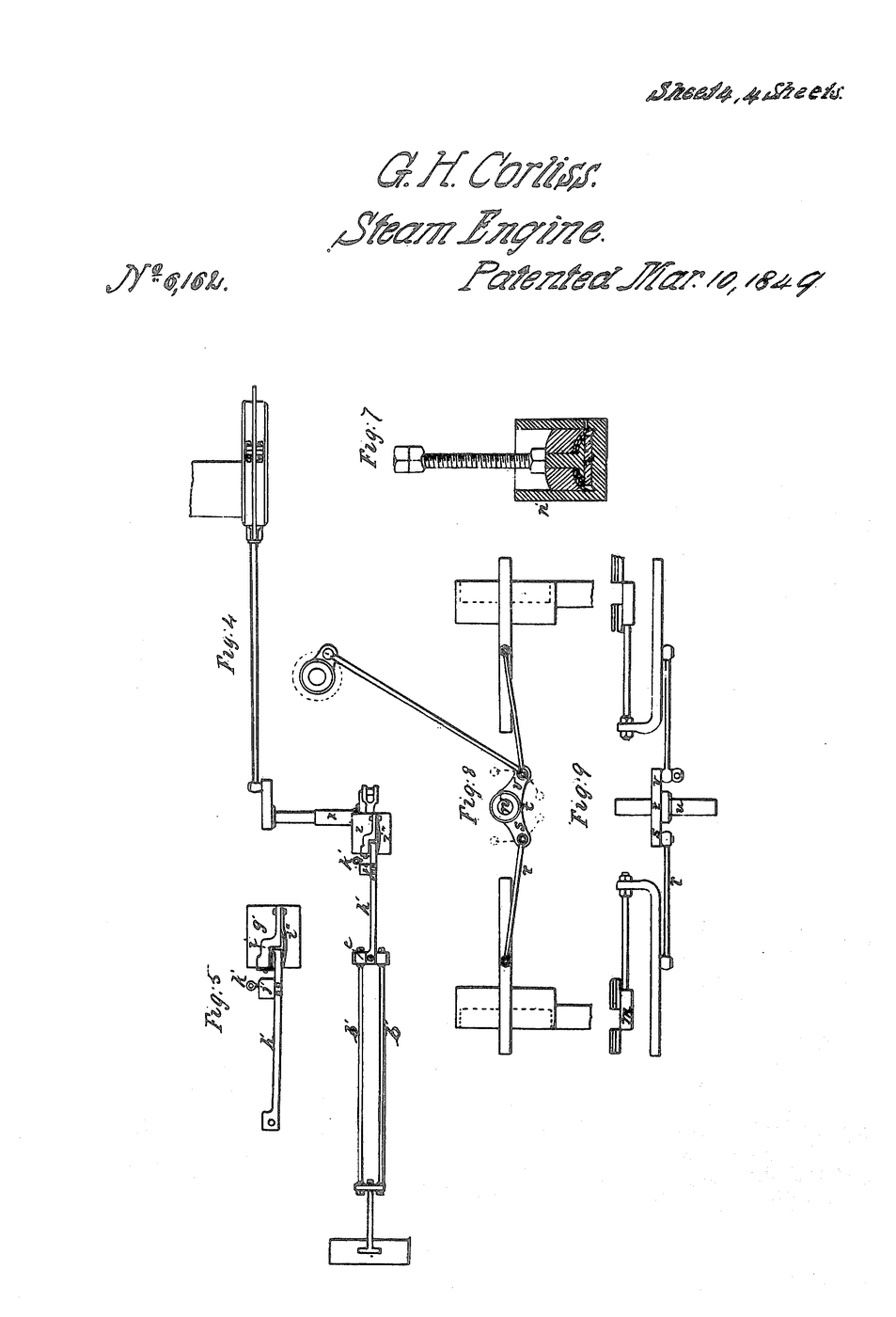
Эдгээр загварууд мэдлэг хуваалцдаг — арга техник, материал эсвэл зарчим

CC0 Нийтийн домэйн
Энэ загвар CC0 дор гаргагдсан. Та зөвшөөрөл авахгүйгээр хуулах, өөрчлөх, түгээх, ашиглах боломжтой.
Загвараар дамжуулан бүтээгдэхүүн худалдаж авч Бүтээгчийг дэмжээрэй Бүтээгчийн шимтгэл Борлуулагчаар тогтоосон, эсвэл энэ загварын шинэ хувилбар үүсгэж орлогоо хуваахын тулд өөрийн загварт холбоос болгон оруулна уу.