ARTE
BELLEZA Y BIENESTAR
ARTESANÍA
CULTURA E HISTORIA
ENTRETENIMIENTO
MEDIO AMBIENTE
COMIDA Y BEBIDAS
FUTURO VERDE
INGENIERÍA INVERSA
CIENCIAS
DEPORTES
TECNOLOGÍA
TECNOLOGÍA VESTIBLE
Traducido
BLUEPRINT NFT

Parpadeante LED — Tu Primer Proyecto Arduino
¡El clásico primer proyecto de electrónica! Construye un circuito LED parpadeante usando un Arduino, una placa de pruebas, una resistencia y un único LED. Perfecto para principiantes absolutos — no se requiere soldadura.
Instrucciones
1
1
Reúne Tus Componentes
Reúne Tus Componentes
Recopila todos los componentes listados a continuación. No se requiere soldadura — todo se conecta a la placa de pruebas.
Materiales para este paso:
 SparkFun Inventor's Kit - V3.21 kit
Arduino Uno R31 pieza
5mm LED (any color)1 pieza
 220 ohm Resistor (1/4W)1 pieza
Breadboard1 pieza
Jumper Wires (Male-to-Male)2 piezas
USB-B Cable1 pieza
Herramientas necesarias:
Computer with Arduino IDE
2
2
Esquema del Circuito
Esquema del Circuito
La señal fluye desde Arduino Pin 13 → resistor 220Ω (R1) → LED (D1) → GND. La resistencia limita la corriente para proteger el LED.
Materiales para este paso:
Arduino Uno R31 pieza
5mm LED (any color)1 pieza
220 ohm Resistor (1/4W)1 pieza3
3
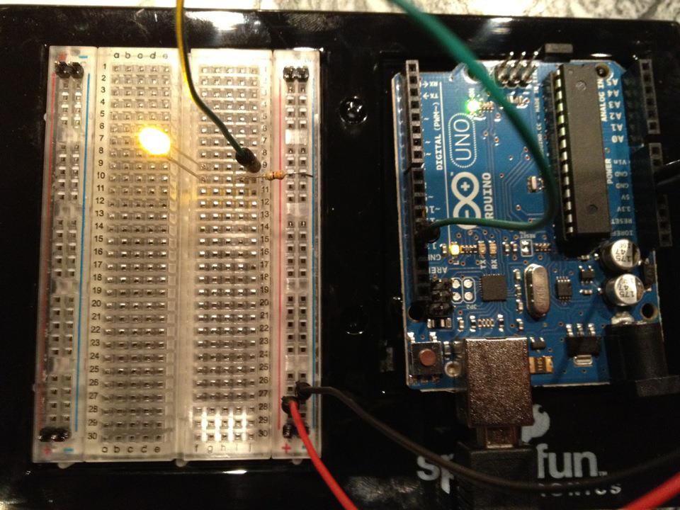
Conéctalo
Conéctalo
- Inserta el LED en la breadboard — pata larga (ánodo +) en una fila, pata corta (cátodo −) en la siguiente.
- Inserta una pata del resistor 220Ω en la misma fila que el cátodo del LED. Otra pata en una fila separada.
- Cable jumper desde la fila del ánodo LED → Arduino Pin 13.
- Cable jumper desde la fila libre del resistor → Arduino GND.
Materiales para este paso:
5mm LED (any color)1 pieza
220 ohm Resistor (1/4W)1 piezaBreadboard1 pieza
Jumper Wires (Male-to-Male)2 piezas
4
4
Subir el Código Blink
Subir el Código Blink
Conecta Arduino vía USB. Abre Arduino IDE, selecciona Tools → Board → Arduino Uno, pega el código y haz clic en Upload.
blink.inoarduino
Materiales para este paso:
Arduino Uno R31 pieza
USB-B Cable1 pieza
Herramientas necesarias:
Computer with Arduino IDE
5
5
PCB Diseño (Referencia)
PCB Diseño (Referencia)
Esto muestra el circuito como un diseño PCB. No es necesario para este proyecto — la placa de pruebas funciona perfectamente — pero muestra cómo se vería el mismo circuito si se fabricara como una placa real.
6
6
Prueba y Experimento
Prueba y Experimento
LED parpadea? ¡Felicitaciones! Acabas de programar hardware.
Solución de problemas:
Próximos experimentos:
Solución de problemas:
- ¿LED no se enciende? Voltea LED — pata larga hacia Pin 13.
- ¿LED permanece encendido? Verifica que el código se haya cargado exitosamente.
- ¿No pasa nada? Verifica que el cableado coincida con el esquema en el Paso 2.
Próximos experimentos:
- Cambia los valores de
delay()para controlar la velocidad de parpadeo - Añade un segundo LED en Pin 12
- Reemplaza con un RGB LED (ver SIK Circuito 3)
Materiales
7- MX$1,826.00
- Marcador de posición
Total estimado
MX$1,826.00Related blueprints
Other builds that share materials, tools, or techniques with this one.

Using a Shift Register — SIK Circuit 14electronics/active
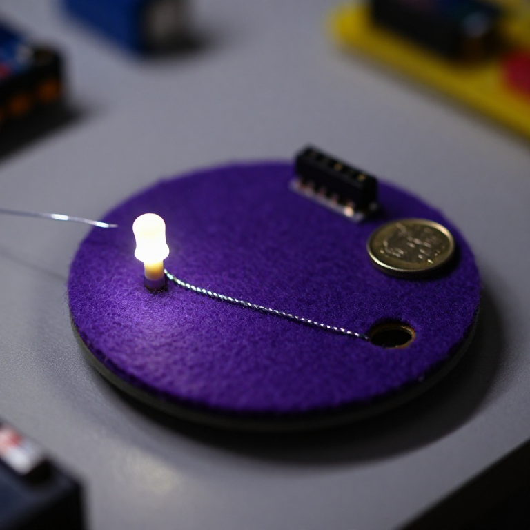
Blinking an LED with LilyPad Arduinoelectronics

Making Charcoal — The First Chemical Processmaterials
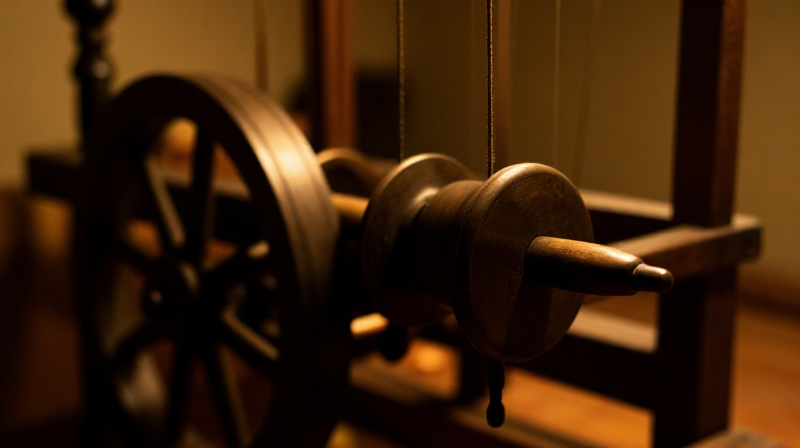
The Spinning Jenny — Multi-Spindle Yarn Productiontextiles
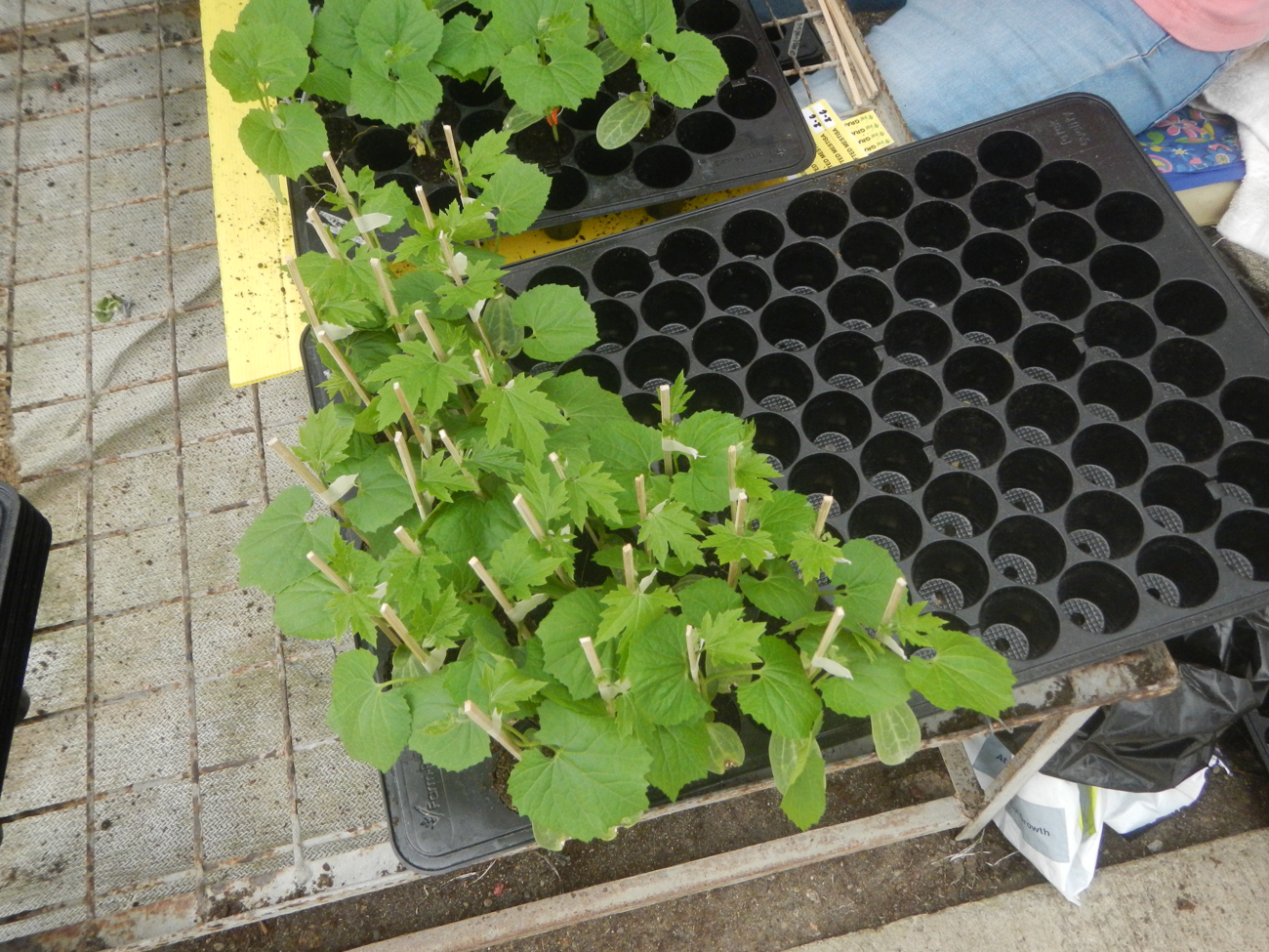
Starting Seeds Indoors — Raising Seedlings for a Head Start
Driving a Motor — SIK Circuit 12electronics/electromech
CC0 Dominio público
Este Blueprint se publica bajo CC0. Eres libre de copiar, modificar, distribuir y usar este trabajo para cualquier propósito, sin pedir permiso.
Apoya al Maker comprando productos a través de su Blueprint, donde gana una Comisión del Maker establecida por los vendedores, o crea una nueva iteración de este Blueprint e inclúyela como conexión en tu propio Blueprint para compartir ingresos.