Building an Aeolipile — Hero's Steam-Powered Spinning Sphere
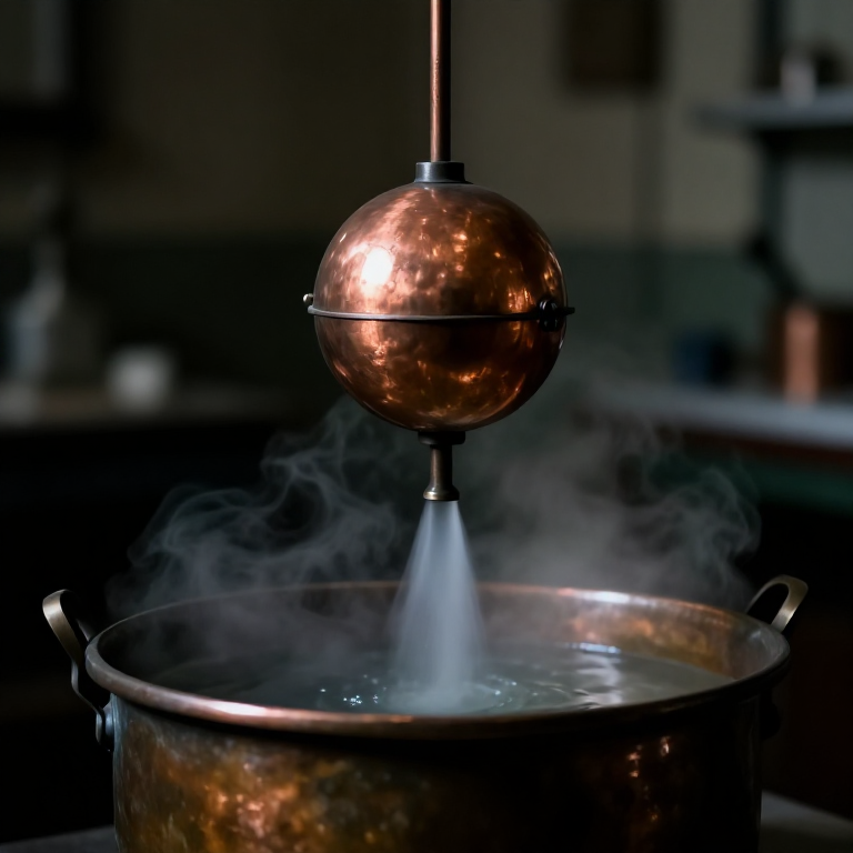
The aeolipile (αἰολίπυλη — 'ball of Aeolus', the Greek god of wind) is a sealed hollow sphere mounted on a pivot above a boiling cauldron. Steam from the cauldron enters the sphere through the pivot tubes, fills the interior, and escapes through two small bent nozzles mounted at opposite ends of the sphere's equator, oriented in opposite rotational directions. The escaping steam produces thrust by Newton's third law — the sphere spins in reaction to the jets, exactly as a lawn sprinkler spins in reaction to water jets. It is the first documented demonstration of jet propulsion and the first machine to convert thermal energy (steam) into mechanical rotary motion.
Hero of Alexandria described the device in 'Pneumatica' (1st century CE), where it appears as a demonstration of the power of steam rather than a practical power source. This has puzzled historians: the Romans had all the materials and knowledge to scale up the aeolipile into a useful steam engine 1,700 years before Watt, yet they did not. The reasons are debated — cheap slave labour removed economic pressure to mechanise, bronze casting was expensive, materials science was insufficiently developed to safely contain higher pressures at scale, and no theoretical framework existed for understanding thermodynamic efficiency. The aeolipile remained a philosophical curiosity rather than an industrial catalyst.
The device nonetheless demonstrates all three core principles of the industrial steam engine: a closed boiler, steam under pressure, and mechanical work extracted from the steam's kinetic energy. When James Watt patented his separate condenser in 1769, he was working from first principles established by Hero in the 1st century CE. The aeolipile spins today in school demonstrations using the same geometry Hero described, a reminder that scientific insight without economic driver can wait millennia before changing the world.
Instrucciones
Understand the physics of jet propulsion
Understand the physics of jet propulsion
Newton's third law states that for every action there is an equal and opposite reaction. Steam exiting the aeolipile nozzles at high velocity is the action — the sphere receives a reaction force in the opposite direction. The two nozzles point in opposite rotational directions (one clockwise, one counter-clockwise when viewed from the top), so both reactions push the sphere in the same rotational sense and it spins. The torque produced equals the mass flow rate of steam multiplied by the exhaust velocity multiplied by the nozzle radius from the spin axis.
At 100°C and atmospheric pressure (the conditions inside a boiling-water aeolipile), steam exits the nozzle at a velocity determined by the pressure differential between inside (atmospheric + slight boiler pressure from water head) and outside (atmospheric). The pressure differential is very small — typically 0.01–0.05 bar gauge — giving exit velocities of 10–30 m/s. This is enough to spin a lightweight copper sphere at several hundred RPM but produces negligible useful torque. A practical steam engine requires much higher boiler pressure (Watt's engine operated at 1–2 bar, modern boilers at 10–200 bar) and a mechanism to capture work from the steam expansion rather than simply exhausting it.
Select copper sheet and tools for sphere forming
Select copper sheet and tools for sphere forming
Copper (pure Cu, melting point 1,083°C) is the ideal material — it is malleable enough to be formed by hand hammering, has good thermal conductivity (helping the sphere heat up quickly from the steam entering through the pivot tubes), and solders readily with tin-lead solder. Use 0.8–1.0 mm thick annealed copper sheet. Annealed copper (heated to 400–600°C and quenched in water) is fully soft and formable; as-rolled copper work-hardens and cracks when hammered into curved shapes.
For a sphere 10 cm in diameter — the approximate size shown in ancient depictions — calculate the flat circle diameter needed: each hemisphere is formed from a disc of approximately 17.5 cm diameter (half the sphere surface area flattened out is π × r² = π × 25 = 78.5 cm², with a disc of radius 5 cm = 78.5 cm², so disc diameter = 2 × √(78.5/π) ≈ 10 cm adjusted for stretching... in practice, cut discs of 17–18 cm to allow for stretching and trimming). Cut two discs of this size with tinsnips.
Herramientas necesarias:
 Sharp Knife
 Hammer (2 kg)
Anneal the copper sheet and form the hemispheres
Anneal the copper sheet and form the hemispheres
Anneal each copper disc by heating it uniformly over a charcoal fire to bright orange-red colour (approximately 550–650°C — do not reach cherry red or the copper begins to scale and weaken) and then quenching immediately in cold water. This fully softens the work-hardened rolled copper for shaping. Work quickly after annealing — copper work-hardens as you hammer it, and after 15–20 hammer blows the sheet will stiffen and require re-annealing to continue forming without cracking.
To form a hemisphere, place the annealed disc over a hardwood dapping block (a block with a hemispherical depression of the correct diameter) and drive it into the depression with a ball-peen hammer, working from the centre outward in concentric circles. Alternatively, work over a steel dome stake (a rounded anvil) using a series of overlapping hammer blows to stretch the metal into the curved shape. After each annealing-and-hammering sequence, trim the ragged edge to a consistent circle with tinsnips. Three to four anneal-and-form cycles typically produce a hemisphere of the correct depth from a flat disc.
Materiales para este paso:
 Lump Charcoal (Hardwood)2 kg
Drill the pivot tube holes and nozzle positions
Drill the pivot tube holes and nozzle positions
Before joining the hemispheres, drill the four required holes in the correct positions while the pieces are still flat and accessible. The two pivot tube holes are drilled at the north and south poles of the sphere — in the centre of each hemisphere cap. These holes receive the bronze pivot tubes that form the steam inlet path and the rotation axle. Drill each pivot hole to exactly the outer diameter of the pivot tube (8 mm for a 6 mm ID tube with 1 mm wall) so the tube is a snug press fit before soldering.
The two nozzle holes are drilled at the equator — the seam between the two hemispheres. Mark the equatorial positions 180° apart from each other (opposite sides of the sphere) and offset 90° from the pivot axis. Drill 3 mm holes for the nozzle tubes. The nozzles must be on opposite sides AND pointing in opposite tangential directions — this is the geometry that produces net rotation. Verify the nozzle orientation before soldering by holding the hemisphere up and checking that the nozzle holes point in tangential (not radial) directions.
Herramientas necesarias:
 Awl
AwlSolder the nozzle tubes into the equatorial holes
Solder the nozzle tubes into the equatorial holes
Each nozzle is a short copper tube 3 mm internal diameter, approximately 2 cm long, with the outer end bent at 90° to point tangentially (in the plane of the sphere's equator). Bend the nozzle tubes before installation — soft-anneal each tube by heating to red and quenching, then bend carefully over a cylindrical mandrel to avoid kinking. The bend radius should be at least three times the tube diameter (3 × 3 mm = 9 mm) to prevent the inner wall from collapsing and restricting the steam jet.
Solder the straight end of each nozzle into its equatorial hole using tin-lead solder (60% tin, 40% lead, melting point approximately 188°C). Apply flux to the joint surfaces first (rosin flux or olive oil flux), heat gently with a charcoal ember until the solder melts and wicks into the gap by capillary action, then remove heat and allow to cool without disturbing. An improperly soldered nozzle joint will leak steam in operation — any visible porosity or cold-solder dullness requires removal and re-soldering before assembly.
Solder the pivot tubes into the pole holes
Solder the pivot tubes into the pole holes
The pivot tubes are straight bronze tubes approximately 8 cm long and 6 mm internal diameter, press-fitted through the north and south pole holes of the hemispheres. They serve two simultaneous functions: they are the axle on which the sphere spins in its support frame bearings, and they are the steam inlet path — steam from the cauldron enters the south pivot tube, flows through the hollow sphere interior, and exits as jets through the nozzles (some steam also escapes through the bearing clearance at the pivot journals, which is normal and unavoidable in the ancient design).
Solder each pivot tube into its hemisphere pole with tin-lead solder, ensuring the tube extends equally through the hole so its end sits flush with the inside of the hemisphere surface — no internal protrusion that would impede steam flow. Allow both soldered hemispheres to cool completely before proceeding to sphere assembly.
Solder the two hemispheres together
Solder the two hemispheres together
Fit the two hemispheres together at the equator with the nozzle tubes installed. The hemisphere rims must fit tightly together — use a mallet to gently close any gaps. Apply flux around the entire circumferential seam and run a bead of solder around the equatorial joint, working in 5 cm sections and allowing each section to cool before moving to the next to prevent heat accumulation that could weaken previous solder joints.
After soldering, fill the completed sphere with water and hold it inverted above a white surface — any water drops that appear indicate leaks. Mark each leak and re-solder individually after drying. A steam-tight sphere requires zero leaks visible at atmospheric pressure. The final sphere should feel rigid and drum-tight when tapped. Check that the pivot tubes are aligned on a common axis by rolling the sphere along a flat surface — the sphere should track straight without wobble if the pivot tubes are truly co-axial.
Build the cauldron stand and pivot support frame
Build the cauldron stand and pivot support frame
The cauldron (the boiler) is a bronze or iron pot with a close-fitting lid, approximately 20 cm diameter and 15 cm deep, with a capacity of 2–3 litres of water — enough for 30–40 minutes of operation before the water needs refilling. The lid must seal well enough to allow slight steam pressure to build (just enough to drive steam up the pivot tube) while being easily removable for refilling. Solder or forge a central hole in the lid for the south pivot tube to pass through with a close but non-touching fit — the tube must rotate freely in the lid hole.
Build a support frame from iron rod or heavy bronze wire: a U-shaped arch straddling the cauldron with two bearing holes at the apex, one on each side of the frame top, aligned on the same axis. The pivot tube ends of the sphere rest in these bearing holes and the sphere spins between the two uprights of the arch. The bearing holes must be smooth and slightly larger than the pivot tube outer diameter — 9 mm holes for 8 mm tubes — to allow free spinning with minimal side-play.
Materiales para este paso:
 Iron Nails10 piezas
Connect the south pivot tube to the cauldron steam outlet
Connect the south pivot tube to the cauldron steam outlet
The south (lower) pivot tube is the steam inlet. It passes through the cauldron lid bearing into the cauldron's steam space above the boiling water. The steam from the boiling cauldron rises into the south pivot tube, travels up through the bearing (with some leakage around the rotating pivot), and enters the hollow sphere interior. Inside the sphere, steam pressure equalises rapidly and drives simultaneous jets from both nozzles. The north (upper) pivot tube vents to atmosphere through the upper bearing — it serves only as the rotation axle, not as a sealed steam path.
The connection at the cauldron lid must allow the sphere (and its pivot tube) to rotate freely while maintaining a loose steam-transmitting fit. This is accomplished simply by making the lid hole slightly larger than the tube and accepting that some steam leaks around the spinning journal — this is the same bearing design used in the historical device, and it works because the slight leakage does not significantly reduce the steam flow to the sphere. Do not attempt to seal the pivot journal — a sealed rotating joint would require packing and would create enough friction to stop the sphere spinning.
First firing and rotation test
First firing and rotation test
Fill the cauldron with 2 litres of water and place it over a charcoal fire. Do not seal the cauldron lid before heating — allow the air inside to exhaust freely as the water heats. When the water approaches boiling (visible steam from the lid hole), seat the sphere on the support frame bearings and place the lid (with the sphere now sitting above it) on the cauldron. As the water boils, steam pressure in the cauldron builds slightly above atmospheric, pushing steam up through the south pivot tube into the sphere.
Within 30–60 seconds of seating the sphere, it should begin to rotate. Rotation starts slowly (10–20 RPM) and accelerates as the sphere warms up and the steam flow rate increases. Observe: the sphere should spin smoothly and consistently in one direction — the direction opposite to the nozzle jet direction. Any wobbling or erratic motion indicates the pivot tubes are not co-axial or the sphere is not balanced. At full steam (water at a rolling boil), a well-built 10 cm copper aeolipile typically reaches 500–1,500 RPM — fast enough that the nozzle jets are visible as blurs and the spinning sphere produces a faint whirring sound.
Materiales para este paso:
Lump Charcoal (Hardwood)3 kgCalculate the mechanical output and efficiency
Calculate the mechanical output and efficiency
The aeolipile converts approximately 1% of the heat input into mechanical work — a thermodynamic efficiency so low it explains why Hero did not pursue it as a practical engine. Calculate it: the charcoal fire inputs roughly 500 W of heat (100 g of charcoal per hour × 7,000 kcal/kg ≈ 800 W, with only 60% transferred to the water ≈ 500 W). The rotating sphere at 1,000 RPM and a nozzle radius of 5 cm produces a peripheral nozzle velocity of 2π × 0.05 × 1,000/60 ≈ 5.2 m/s. The steam mass flow (estimated 5 g/min = 0.083 g/s) at exit velocity 20 m/s produces a thrust force of 0.083 × 10⁻³ × 20 = 1.7 × 10⁻³ N per nozzle, and mechanical power = force × nozzle speed = 0.0017 × 5.2 ≈ 9 mW per nozzle. Two nozzles ≈ 18 mW, or 0.018/500 = 0.004% efficiency.
This calculation demonstrates why the aeolipile could not have powered practical machinery in antiquity — 18 mW cannot grind grain or lift stone. However, the physics understanding Hero captured — the directional exhaust of a fluid producing motion in the opposite direction — is identical to the principles of jet aircraft engines, rocket thrusters, and steam turbines operating 2,000 years later.
Safety considerations for steam under pressure
Safety considerations for steam under pressure
The aeolipile as described operates at very low pressure — typically 0.02–0.05 bar gauge above atmospheric — because the cauldron lid is not sealed, merely rested on the pot with the pivot tube forming a loose-fitting connection. At these pressures the device is inherently safe: steam escapes around the pivot journal and lid rim as fast as the fire generates it, and internal pressure never accumulates to dangerous levels. Do not modify the design to seal the cauldron more tightly in an attempt to increase pressure — even a partially sealed lid can accumulate enough pressure from a charcoal fire to cause a violent steam release if the sphere or a solder joint fails.
Keep hands away from the nozzle jet positions while the device is operating — steam at 100°C exiting at 20 m/s causes contact burns. Allow the sphere to cool for at least five minutes after removing from the fire before handling. Store the cauldron empty and the sphere separately — water left standing in a sealed copper vessel (even at room temperature) creates mildly acidic conditions that corrode internal solder joints over months of storage.
Materiales de Blueprints conectados
Blueprints relacionados
Estos blueprints comparten conocimiento — técnicas, materiales o principios
Related blueprints
Other builds that share materials, tools, or techniques with this one.

CC0 Dominio público
Este Blueprint se publica bajo CC0. Eres libre de copiar, modificar, distribuir y usar este trabajo para cualquier propósito, sin pedir permiso.
Apoya al Maker comprando productos a través de su Blueprint, donde gana una Comisión del Maker establecida por los vendedores, o crea una nueva iteración de este Blueprint e inclúyela como conexión en tu propio Blueprint para compartir ingresos.