

Fleming Valve
A radio wave arriving at an aerial produces an alternating current — swinging one way then the other, millions of times a second. Any meter or earpiece you connect simply sits still, because the average of that swing is zero. The signal is present and completely unreadable.
To detect it you need a component that conducts one way and not the other. Rectify the oscillation and the swing becomes a lopsided current with a genuine average, and that average can move a needle or a diaphragm. In 1905 no such component existed for these frequencies.
Fleming's answer uses a hot wire in a vacuum. Heat a filament until it glows and it throws off charge; a cold plate nearby will accept that charge, but the cold plate will not throw any back. The gap is a one-way street — a valve, in the plumbing sense, and that is what he called it.
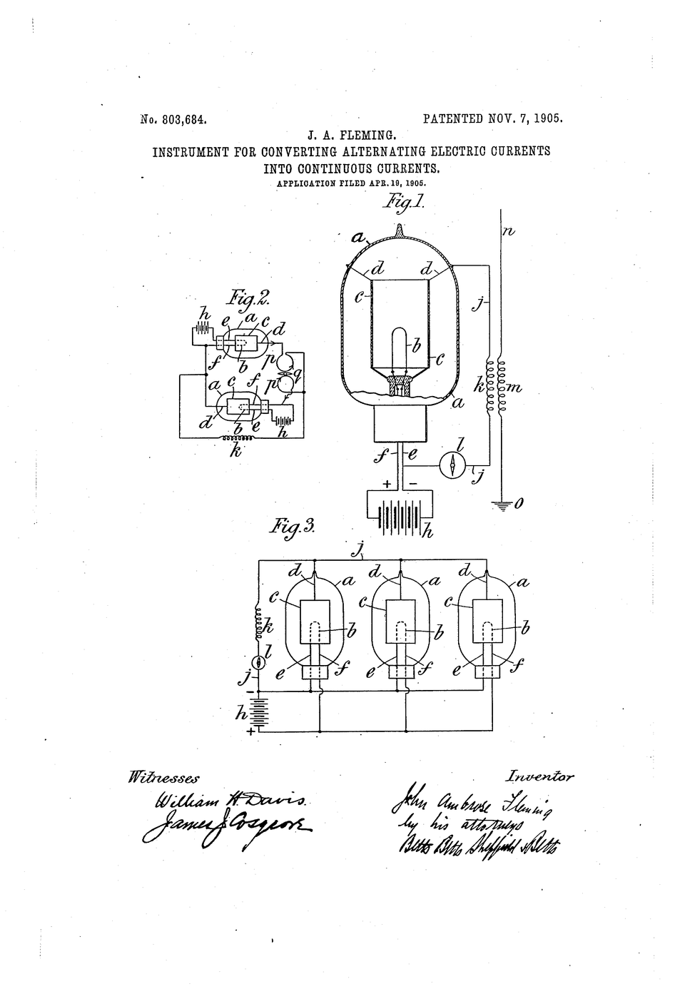
US Patent 803,684, "Instrument for Converting Alternating Electric Currents into Continuous Currents", filed 19 April 1905 and granted 7 November 1905 to John Ambrose Fleming. He states it exactly: "negative electricity can pass from the hot conductor to the cold conductor, but not in the reverse direction."
Instrucciones
Low voltage only, and mind the heat
Low voltage only, and mind the heat
Run the heater at its rated voltage and keep the plate supply at 24 V or less. Classic valve circuits use hundreds of volts and are not a beginner's project. The glass gets hot — let it cool before handling.
Read US 803,684 and find the word unilateral
Read US 803,684 and find the word unilateral
Fleming claims the space between a hot and a cold conductor "possesses a unilateral electric conductivity". The vacuum is the component — the metal parts only define it.
Try to read an AC signal directly
Try to read an AC signal directly
Put a low-voltage AC source across a moving-coil meter on a DC range. The needle sits near zero however large the signal is. This is the problem.
Herramientas necesarias:
 Multímetro digital — autorrango, verdadero valor eficaz
Identify the valve's pins
Identify the valve's pins
Use a small vacuum diode and its datasheet. Find heater, cathode and anode before wiring anything — a heater on the anode pins destroys the valve.
Herramientas necesarias:
 Válvula diodo de vacío
Power the heater alone and watch it glow
Power the heater alone and watch it glow
Bring the heater up to rated voltage and nothing else. A dull orange glow appears. That glow is the whole mechanism starting.
Herramientas necesarias:
 Fuente de alimentación de banco
Connect the anode positive and measure
Connect the anode positive and measure
Put 12 V between anode and cathode, anode positive, through a 10 kΩ resistor. Record the current. It flows.
Reverse the supply and measure again
Reverse the supply and measure again
Swap the leads so the anode is negative. The current falls to essentially nothing. Same components, same voltage, no conduction.
Turn the heater off and repeat both directions
Turn the heater off and repeat both directions
With a cold filament nothing conducts either way. The one-way behaviour exists only while something is hot enough to emit — it is not a property of the metal.
Plot current against anode voltage
Plot current against anode voltage
Step the anode from 0 to 24 V and record current at each step. The curve rises, then flattens — beyond a point, every emitted charge is already being collected.
Raise the heater voltage slightly and re-plot
Raise the heater voltage slightly and re-plot
Run the heater a little hotter within its rating. The flat part sits higher: a hotter filament emits more. The cathode sets the ceiling, the anode only collects.
Feed AC in and read the output
Feed AC in and read the output
Replace the DC supply with a low-voltage AC source across the valve and resistor. The meter that read zero in step 3 now reads a real DC value.
Add a smoothing capacitor
Add a smoothing capacitor
Put a capacitor across the resistor. The pulsing output becomes steady — rectification plus smoothing is how every valve radio got its supply.
Compare against a semiconductor diode
Compare against a semiconductor diode
Swap in a silicon diode and repeat step 11. Same one-way behaviour, no heater, no warm-up, no glass. Note what it cost the valve to do the same job.
Confirm it does not amplify
Confirm it does not amplify
Try to make the output larger than the input. You cannot. A valve with two electrodes can only rectify — and that limit is what the next invention removed.
History & Context — a lamp with a plate in it
History & Context — a lamp with a plate in it
The patent. US 803,684, "Instrument for Converting Alternating Electric Currents into Continuous Currents", filed 19 April 1905 and granted 7 November 1905 to John Ambrose Fleming. The word valve is Fleming's own analogy — a one-way valve in a pipe — and it is why British usage still says valve where American usage says tube.
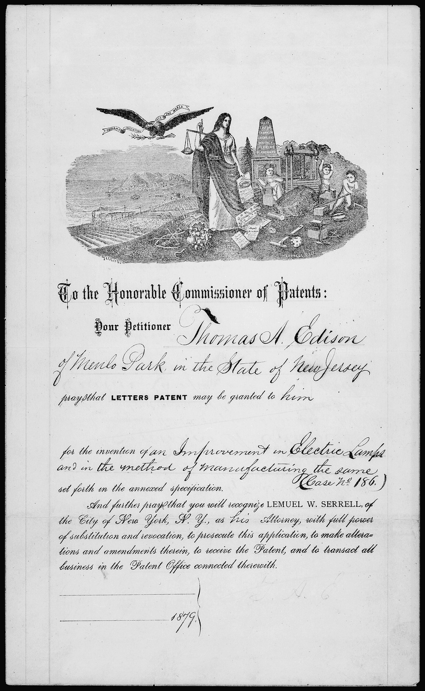
The device is an incandescent lamp with an extra electrode. That is not a figure of speech. In 1883 Edison, investigating why his lamps blackened, sealed a metal plate into a bulb beside the filament and found that current would flow from the hot filament to the plate but not back. He patented the observation, could not explain it, and put it aside; it became known as the Edison effect. Fleming had been a consultant to the Edison companies and knew the effect intimately, and he was separately working for Marconi on the problem of detecting weak wireless signals. His contribution was to recognise that a laboratory curiosity in lamp manufacture was exactly the missing component in radio. It is a clean example of an invention that is not a new phenomenon but a new use for a known one — and of why cross-domain experience is worth so much.
Why heat is doing the work. A metal at room temperature holds its free electrons; heat it enough and some escape the surface entirely, forming a cloud around it. A positively charged plate sweeps that cloud up, so current flows. Reverse the polarity and the cold plate is asked to supply electrons of its own — and having no cloud, it supplies almost none. The asymmetry is between hot and cold, not between two different materials, which is why step 8 is the decisive test: kill the heater and the component stops being a component. The flattening in step 9 is the second half of the same story — once the plate collects everything the filament is emitting, raising the voltage cannot produce current that does not exist.
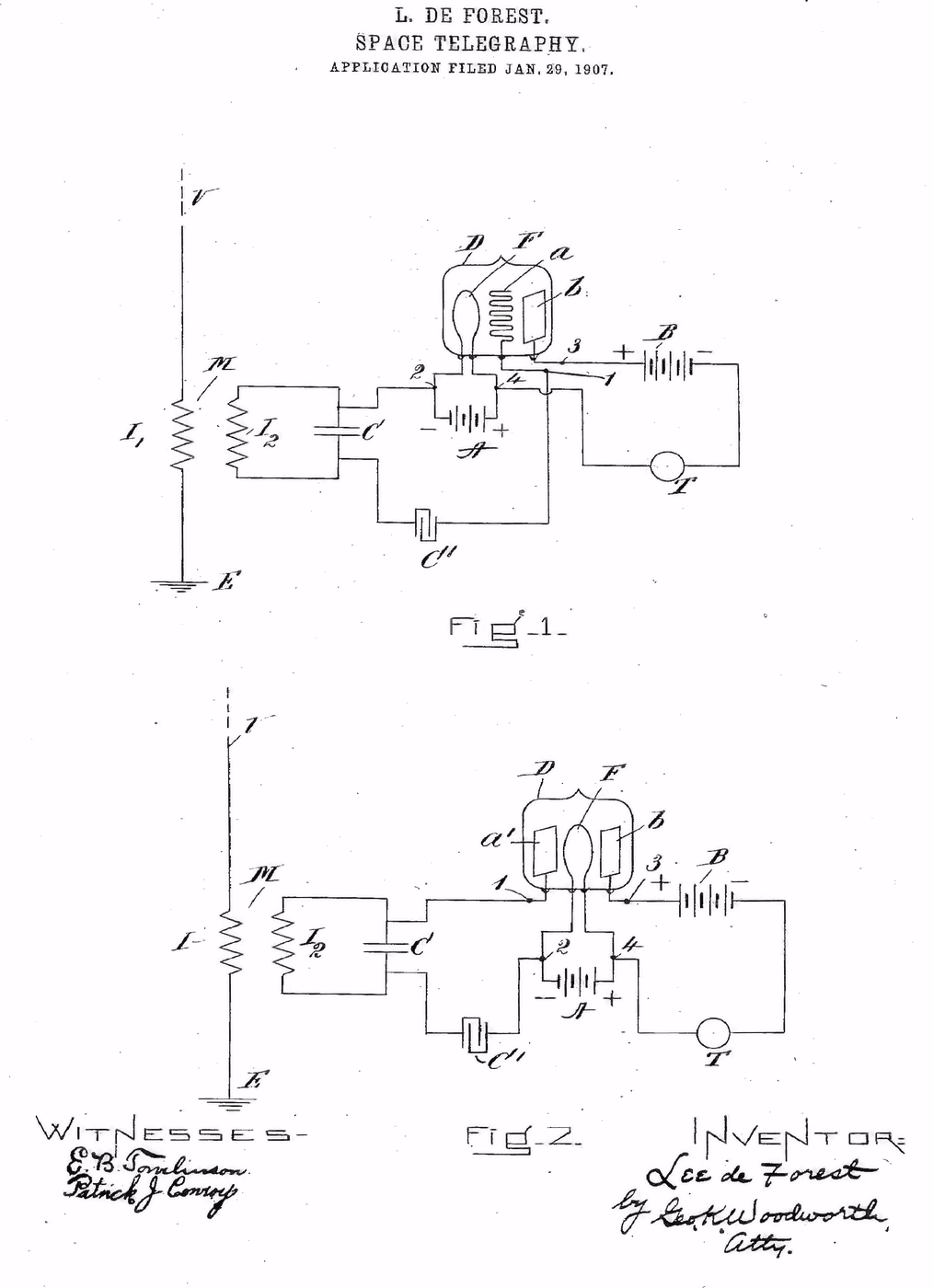
What it could not do. Two electrodes give you a switch that is always in the same position: current either flows or does not, and nothing controls how much. Adding a third electrode — a grid between filament and plate, where a small voltage steers a large current — turns the valve into an amplifier, and that is Lee de Forest's Audion of 1906. The two men and their backers litigated over the relationship for years. Both devices are in this collection, and the honest summary is that de Forest's is unmistakably built on Fleming's, and that Fleming's is unmistakably built on Edison's.
The straight line to now. Rectification is still the first thing that happens inside almost every mains-powered device you own, and the silicon diode in step 13 performs Fleming's function with no heater, no vacuum and no warm-up. The valve's descendants ran radio, radar, television and the first electronic computers for fifty years, and were replaced by the transistor — also in this collection — which does the same jobs cold.
Herramientas requeridas
3- Marcador de posición
- Marcador de posición
- Marcador de posición
Materiales de Blueprints conectados

Blueprints relacionados
Estos blueprints comparten conocimiento — técnicas, materiales o principios

CC0 Dominio público
Este Blueprint se publica bajo CC0. Eres libre de copiar, modificar, distribuir y usar este trabajo para cualquier propósito, sin pedir permiso.
Apoya al Maker comprando productos a través de su Blueprint, donde gana una Comisión del Maker establecida por los vendedores, o crea una nueva iteración de este Blueprint e inclúyela como conexión en tu propio Blueprint para compartir ingresos.