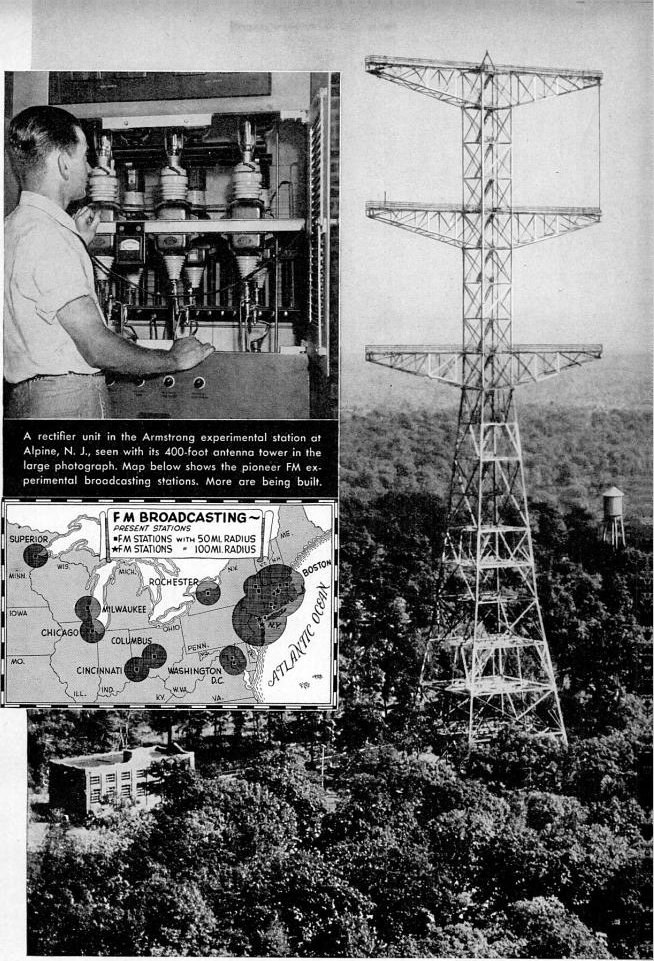


Frequency Modulation
Instrucciones
Show where noise lives on an AM carrier
Show where noise lives on an AM carrier
Understand the enemy before designing around it.
- Generate an amplitude-modulated carrier and view it on the oscilloscope — a sine wave whose envelope carries the audio.
- Inject a brief impulse into the signal path, simulating a spark or lightning.
- Detect the AM and listen to the recovered audio.
- Now look at the envelope on the scope during the impulse.
The impulse rides directly on the envelope, and because an AM detector recovers exactly that envelope, the click passes straight through to the listener. No amount of filtering after detection helps, because by then the click and the programme are the same kind of thing.
This is why AM broadcast is unlistenable during a thunderstorm and why a car AM radio buzzes under power lines. It is not a defect of any particular receiver — it is a consequence of using amplitude to carry the message, which is exactly what atmospheric noise also arrives as.Materiales para este paso:
 Juego de resistencias1 kit
 Kit de condensadores1 kit
 Placa perforada / placa de prototipos1 pieza
 Alambre de soldadura1 reel
Herramientas necesarias:
 Generador de señales
 Generador de funciones
 Osciloscopio
 Analizador de espectro / software FFT
 Multímetro digital de laboratorio
 Estación de soldadura
 Gafas de seguridad transparentes
Modulate frequency instead, with a varactor
Modulate frequency instead, with a varactor
Build the transmitter side and watch the carrier move.
- Build a stable LC oscillator at a convenient frequency — a few MHz is easy to work with.
- Include a varactor diode as part of the tuning capacitance — a reverse-biased diode whose junction capacitance varies with applied voltage.
- Apply an audio signal to the varactor bias and observe the oscillator output on a spectrum analyser.
- Measure how far the carrier moves for a given audio amplitude.
The carrier amplitude stays constant while its frequency sweeps back and forth in step with the audio. That swing is the deviation, and it — not the audio amplitude — is what now carries loudness.
Deviation is a design choice, and it is the whole argument. Broadcast FM uses ±75 kHz to carry 15 kHz of audio: five times more spectrum than the message strictly needs. That deliberate excess is precisely where the noise advantage comes from, and it is why the narrow-band analysis of the 1920s concluded FM was pointless.
The varactor is a modern convenience; Armstrong had to shift a reactance valve or mechanically vary a capacitor. The principle is identical and the varactor simply makes it a two-component job.Materiales para este paso:
 Diodo varactor2 piezas
 Hilo de cobre esmaltado5 mKit de condensadores1 kitJuego de resistencias1 kit
Herramientas necesarias:
OsciloscopioAnalizador de espectro / software FFTGenerador de señalesMultímetro digital de laboratorio Fuente de alimentación de banco ajustable
 Medidor LCR de sobremesaEstación de soldaduraGafas de seguridad transparentes
Look at the spectrum and find the sidebands
Look at the spectrum and find the sidebands
FM spreads energy in a way that surprises everyone the first time they see it.
- Modulate with a single steady audio tone and view the spectrum.
- Count the sidebands either side of the carrier and note their spacing.
- Now increase the deviation while keeping the audio frequency fixed, and watch the pattern change.
- Find a deviation at which the CARRIER itself disappears.
FM produces a theoretically infinite series of sidebands spaced at the modulating frequency, whose amplitudes follow Bessel functions — and at certain modulation indices the carrier amplitude passes through zero entirely. Seeing the carrier vanish while the signal is still being transmitted is genuinely startling, and it is the standard way to calibrate deviation precisely: adjust until the carrier nulls, and you know the index exactly.
In practice the sidebands beyond a certain point are negligible, and Carson’s rule — bandwidth is roughly twice the sum of deviation and highest audio frequency — captures where to stop. For broadcast FM that gives about 180 kHz, close to the 200 kHz channel spacing actually allocated.
This is why AM stations sit 9 or 10 kHz apart and FM stations 200 kHz apart. The spacing is not a regulatory whim, it is Carson’s rule with a guard band.Materiales para este paso:
 Papel milimetrado1 pad
Herramientas necesarias:
Analizador de espectro / software FFTGenerador de señalesOsciloscopioGenerador de funcionesGafas de seguridad transparentesBuild a limiter, and delete the noise
Build a limiter, and delete the noise
This stage is where the whole advantage is collected.
- Build a high-gain amplifier stage that clips hard at both extremes — deliberately overdriven, or a pair of back-to-back diodes across the signal.
- Feed it an FM signal with amplitude noise added.
- Look at the output on the scope.
- Measure the residual amplitude variation before and after.
The output is a constant-amplitude square-ish wave; every trace of the amplitude noise has gone, and the frequency information is completely untouched. That is the trick in one sentence — deliberately destroy the dimension the noise lives in, because you are not using it.
An AM receiver cannot do this, because the amplitude IS the message. FM can, because amplitude carries nothing.
The effect is not gradual. Above a certain signal level the noise essentially disappears and reception is clean; below it, reception collapses abruptly into hiss. That threshold is why FM either sounds perfect or sounds terrible with little in between, while AM degrades smoothly — and it is why FM coverage maps have much sharper edges than AM ones.Materiales para este paso:
 Diodo de germanio (1N34A)4 piezas
 Surtido de transistores1 kitJuego de resistencias1 kitKit de condensadores1 kit
Herramientas necesarias:
OsciloscopioGenerador de señalesAnalizador de espectro / software FFTMultímetro digital de laboratorioFuente de alimentación de banco ajustableEstación de soldaduraGafas de seguridad transparentesDiscriminate frequency back into audio
Discriminate frequency back into audio
Turn frequency variation back into amplitude variation, which is the one thing a detector can handle.
- Build a tuned circuit and deliberately tune it OFF the carrier frequency, so the carrier sits on the sloping side of its response.
- Feed the limited FM signal into it and detect the output with a diode.
- Listen to the recovered audio and measure its distortion.
- Now build a balanced version — two circuits tuned either side of the carrier, their detected outputs subtracted.
The slope detector works and sounds poor; the balanced discriminator works and sounds good. A single slope is only straight over a short span, so large deviations run into its curvature and distort. Two slopes arranged back to back have their curvatures cancel around the centre, giving a long straight region and a null exactly at the carrier.
Notice the shape of the fix: when a transfer characteristic is nonlinear, using two of them in opposition can cancel the nonlinearity while doubling the wanted response. The same idea gives you the push-pull amplifier, the differential pair and the bridge circuit.
Later receivers use the ratio detector, which adds inherent limiting so a separate limiter stage is unnecessary, and modern ones use a phase-locked loop whose control voltage IS the demodulated audio. Three mechanisms, one job — and all three are still in use somewhere.Materiales para este paso:
Hilo de cobre esmaltado10 m Núcleo toroidal de ferrita2 piezasDiodo de germanio (1N34A)4 piezasKit de condensadores1 kitJuego de resistencias1 kit
Herramientas necesarias:
OsciloscopioGenerador de señalesAnalizador de espectro / software FFTMedidor LCR de sobremesaMultímetro digital de laboratorioEstación de soldaduraGafas de seguridad transparentesMateriales
10- Marcador de posición
- 1 kitMarcador de posición
- Marcador de posición
- 1 reelMarcador de posición
- 2 piezasMarcador de posición
- Marcador de posición
- 1 padMarcador de posición
- 4 piezasMarcador de posición
- Marcador de posición
- 2 piezasMarcador de posición
Herramientas requeridas
9- Marcador de posición
- Marcador de posición
- Marcador de posición
- Marcador de posición
- Marcador de posición
- Marcador de posición
- Marcador de posición
- Marcador de posición
- Marcador de posición
Blueprints relacionados
Estos blueprints comparten conocimiento — técnicas, materiales o principios
CC0 Dominio público
Este Blueprint se publica bajo CC0. Eres libre de copiar, modificar, distribuir y usar este trabajo para cualquier propósito, sin pedir permiso.
Apoya al Maker comprando productos a través de su Blueprint, donde gana una Comisión del Maker establecida por los vendedores, o crea una nueva iteración de este Blueprint e inclúyela como conexión en tu propio Blueprint para compartir ingresos.