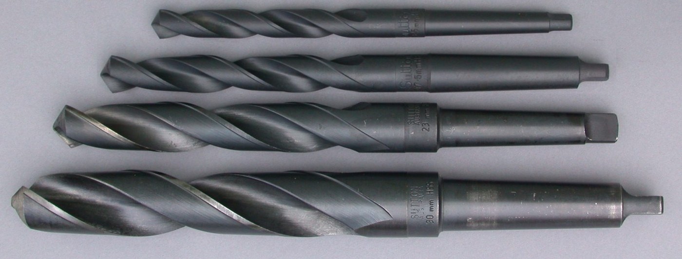


Morse Taper
Instrucciones
Understand the self-locking angle before cutting metal
Understand the self-locking angle before cutting metal
The whole component is one angle, chosen for one reason.
- A Morse taper is about 1 in 20 on diameter — roughly 2.9 degrees included, depending on the size number.
- Compute the friction angle for steel on steel with a coefficient around 0.15: about 8.5 degrees.
- Compare: the taper's half-angle is well BELOW the friction angle, so it self-locks.
- Now recall the cone clutch at 12 degrees half-angle — deliberately above it, so it releases.
One rule, two opposite design intentions. A taper self-locks when its half-angle is less than the friction angle, because the friction force resisting withdrawal exceeds the wedging force trying to push it out. The cone clutch is designed just steep enough to avoid that, so it can be disengaged. The Morse taper is designed comfortably inside it, so it cannot fall out. Same geometry, same equation, opposite requirement.
Write both angles down side by side. Understanding that one number decides whether a taper is a clutch or a chuck is the most transferable thing in this blueprint.Materiales para este paso:
 Papel milimetrado1 pad
Herramientas necesarias:
 Calibre digital de 6 pulgadas
 Escuadra combinada
Cut a matched taper and socket
Cut a matched taper and socket
Both parts to the same angle, and the angle is what must match — not the diameter.
- From 25 mm aluminium round bar, file or turn a male taper 60 mm long at 1 in 20.
- Bore and taper a matching socket in a second piece of bar.
- Blue the male taper and insert it into the socket.
- Withdraw and inspect the transfer — contact should be even along the full length.
- Correct by working the SOCKET, not the male taper, until contact is even.
Contact at the small end only means the socket angle is too steep; contact at the large end means it is too shallow. This is the standard diagnosis and it is read directly from the blue. A taper touching at one end only carries the whole drive load on a narrow band, slips under torque, and bruises both parts.
Work the socket rather than the spindle nose, on the same principle as the sacrificial shaft sleeve — correct the cheaper, more easily replaced part.Materiales para este paso:
 Redondo de aluminio2 piezas
Herramientas necesarias:
 Arco de sierra para metales con hojas
 Tornillo de banco
 Juego de limas
 Taladro inalámbrico
 Juego de brocasCalibre digital de 6 pulgadasEscuadra combinada
Add the tang and the drift slot
Add the tang and the drift slot
A backup drive and a way to get the tool out again.
- File a flat rectangular tang on the small end of the male taper.
- Cut a matching slot through the side of the socket housing.
- Make a tapered steel drift that passes through the slot and bears on the tang's end.
- Test: insert the taper firmly, then tap the drift and confirm the taper releases.
The tang is a backup, not the main drive. Friction on the taper transmits the torque in normal use; the tang only takes over if the taper slips, and if it is doing the driving something is already wrong. Its real everyday job is to give the drift something to push against.
A taper that has once slipped and bruised will slip more readily afterwards, because the bruising reduces contact area. That is why the standard advice is to keep both taper and socket scrupulously clean — a single chip trapped in the socket makes a high spot, breaks the contact pattern, and starts the cycle.Materiales para este paso:
 Pletina de aluminio1 pieza
Herramientas necesarias:
Juego de limasArco de sierra para metales con hojasTornillo de bancoTaladro inalámbricoJuego de brocasCalibre digital de 6 pulgadasMeasure grip and concentricity
Measure grip and concentricity
Two claims — it holds, and it centres. Test both.
- Insert the taper with a firm push and measure the torque needed to make it slip.
- Repeat after a light hammer tap to seat it, and compare.
- Mount a dial indicator against the male taper's outer end and rotate the assembly to measure runout.
- Remove, rotate the taper 120 degrees, refit and measure again.
- Repeat once more and compare all three readings.
Herramientas necesarias:
Calibre digital de 6 pulgadasTornillo de banco Cronómetro
A standard that outlived its inventor's company, and history
A standard that outlived its inventor's company, and history
Stephen A. Morse is better known in this catalogue for the twist drill, which he patented in 1863. The taper followed around 1864 as the way to hold that drill in a machine, and the two inventions are a matched pair: a better drill that no existing chuck could hold properly, and a fitting designed for it.
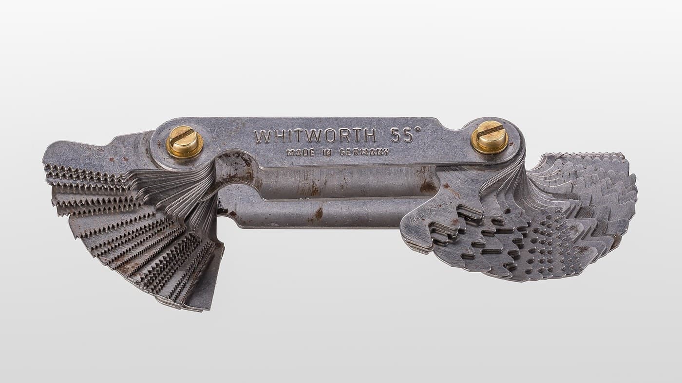
Standardisation is the achievement. Morse tapers are numbered 0 to 7, and a No. 2 shank from any manufacturer fits a No. 2 socket in any machine, anywhere, a century and a half later. This is the same kind of victory as the Whitworth thread twenty years earlier: the technical design is elegant, but the value is that everybody agreed on it. A workshop with standard tapers can buy tooling from anyone.
Where it sits in this batch's chain. The lathe, planer, shaper and mill all need to hold cutting tools rigidly and change them quickly. The Morse taper is the connector that let those machines share tooling, and its arrival in 1864 sits naturally beside the 1862 milling machine and the 1863 twist drill — a cluster of inventions solving one problem from three directions.
Its honest limits, and what replaced it: a self-locking taper needs a drift and space behind the spindle to release it, and it grips ever harder under heavy axial load, sometimes needing real force to part. For machines that change tools automatically, that is unacceptable — so modern machining centres use steeper NON-locking tapers with a drawbar to pull them in and a mechanism to push them out. A different answer, chosen because the requirement changed from “must not fall out” to “must release on command in under a second”.
Materiales
3- 1 padMarcador de posición
- 2 piezasMarcador de posición
- 1 piezaMarcador de posición
Herramientas requeridas
8- Marcador de posición
- Marcador de posición
- Marcador de posición
- Marcador de posición
- Marcador de posición
- 1 vendor sell this, none ship to you yetMarcador de posición
- Marcador de posición
- Marcador de posición
Blueprints relacionados
Estos blueprints comparten conocimiento — técnicas, materiales o principios
CC0 Dominio público
Este Blueprint se publica bajo CC0. Eres libre de copiar, modificar, distribuir y usar este trabajo para cualquier propósito, sin pedir permiso.
Apoya al Maker comprando productos a través de su Blueprint, donde gana una Comisión del Maker establecida por los vendedores, o crea una nueva iteración de este Blueprint e inclúyela como conexión en tu propio Blueprint para compartir ingresos.