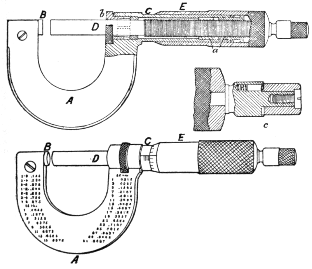


Micromètre
Un atelier ne peut pas fabriquer deux pièces identiques s'il ne sait pas mesurer le millième. Le micromètre est l'instrument qui a rendu la pièce interchangeable possible.
Brevet français n° 7 518, délivré le 7 septembre 1848 à Jean Laurent Palmer, pour le « Système Palmer ». L'idée est simple et profonde : une vis de pas connu transforme une rotation, que l'on peut diviser finement sur un grand cercle, en un déplacement minuscule. Si la vis avance de 0,5 mm par tour et que le tambour porte 50 divisions, chaque division vaut 0,01 mm.
Ce que la légende raconte à tort. On lit partout que Brown & Sharpe ont inventé ou breveté le micromètre en 1867. C'est faux. Joseph R. Brown et Lucien Sharpe ont vu le Système Palmer à l'Exposition universelle de Paris en 1867, en ont acheté un, et en ont copié le principe ; leur instrument est commercialisé en 1868-69. Le brevet est celui de Palmer, et il a vingt ans de plus.
Instrucciones
Comprendre la revendication avant de construire
Comprendre la revendication avant de construire
Palmer ne revendique pas « une pince à mesurer ». Il revendique une amplification : une vis de pas connu convertit un grand angle facile à lire en un petit déplacement difficile à lire. Écrivez cette phrase avant de commencer.
Mesurer le pas d'une vis
Mesurer le pas d'une vis
Prenez une vis #6-32. Comptez 10 tours en la vissant et mesurez l'avance totale à la règle. Divisez par 10 : c'est le pas.
Materiales para este paso:
 Tornillo de máquina n.º 6-321 pieza
Herramientas necesarias:
 Regla
ReglaCalculer la division du tambour
Calculer la division du tambour
Pas divisé par le nombre de divisions du tambour = plus petite lecture. Notez le calcul sur le papier millimétré. Pour 0,5 mm et 50 divisions : 0,01 mm.
Materiales para este paso:
 Papel milimetrado1 hoja
Tracer un tambour de 50 divisions
Tracer un tambour de 50 divisions
Avec le rapporteur, tracez un cercle de 60 mm et divisez-le en 50 parts égales (7,2° chacune). Découpez-le.
Materiales para este paso:
Papel milimetrado1 hojaHerramientas necesarias:
 Transportador de ángulos
 Tijeras
Monter le tambour sur la vis
Monter le tambour sur la vis
Collez le disque sur la tête de la vis, bien centré. Laissez sécher 10 minutes.
Materiales para este paso:
 Cola de carpintero3 ml
Construire le corps
Construire le corps
Percez un avant-trou dans la planche et vissez-y la vis de sorte qu'elle avance contre une butée fixe. C'est l'étrier de Palmer, en bois.
Materiales para este paso:
 Tabla de madera plana1 pieza
Herramientas necesarias:
 Juego de brocas
Tracer un index fixe
Tracer un index fixe
Tracez un trait de référence sur la planche, au bord du tambour. Sans index, une graduation ne veut rien dire.
Herramientas necesarias:
 Rotulador permanente
Étalonner sur zéro
Étalonner sur zéro
Vissez jusqu'au contact de la butée. Tournez le tambour pour amener le zéro en face de l'index. Un instrument non étalonné ment avec précision.
Mesurer une feuille d'aluminium
Mesurer une feuille d'aluminium
Insérez la feuille, vissez jusqu'au contact léger, lisez tours + divisions. Convertissez en millimètres.
Materiales para este paso:
 Papel de aluminio1 hoja
Mesurer une pile de dix feuilles
Mesurer une pile de dix feuilles
Empilez dix feuilles, mesurez, divisez par dix. Comparez à la mesure unitaire : l'écart est votre erreur de lecture, pas l'épaisseur du métal.
Materiales para este paso:
Papel de aluminio10 hojasComparer avec un micromètre réel
Comparer avec un micromètre réel
Mesurez la même feuille au micromètre d'atelier. Notez l'écart avec votre modèle en bois.
Herramientas necesarias:
 Micrómetro
Serrer trop fort, exprès
Serrer trop fort, exprès
Reprenez la mesure en forçant. La lecture change : vous écrasez la matière. Ce défaut sera résolu quarante ans plus tard par le ressort de Starrett.
Materiales para este paso:
Papel de aluminio1 hojaFaire mesurer par quelqu'un d'autre
Faire mesurer par quelqu'un d'autre
Demandez à une autre personne de mesurer la même feuille. L'écart entre vous deux est le véritable problème industriel : la mesure doit être reproductible, pas seulement fine.
Materiales para este paso:
Papel de aluminio1 hojaHistoire et contexte
Histoire et contexte
Brevet français n° 7 518, Jean Laurent Palmer, 7 septembre 1848, délivré par le ministère de l'Agriculture et du Commerce.
Palmer présente un étrier à vis micrométrique lisible directement, sans table ni calcul. L'instrument reste peu diffusé en France.
La correction qui compte. D'innombrables sources attribuent l'invention à Brown & Sharpe en 1867. Les faits : J. R. Brown et L. Sharpe découvrent le Système Palmer à l'Exposition de Paris de 1867, en achètent un exemplaire, et s'en inspirent pour un calibre de tôle ; leur micromètre de poche sort en 1868-69. Ils ont industrialisé et popularisé l'instrument — ce qui est considérable — mais ils ne l'ont pas inventé. Répéter la légende, c'est effacer Palmer d'un fait vérifiable.
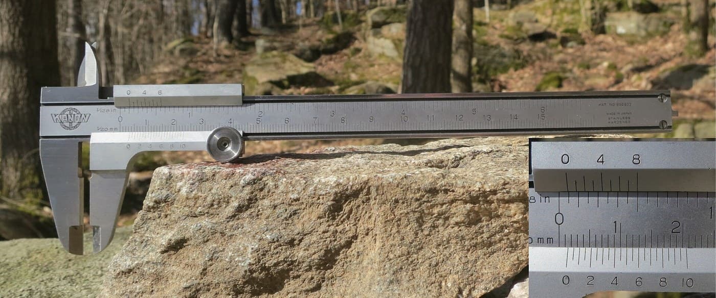
Pourquoi cet instrument change tout. Tant qu'un ajusteur travaille « au senti », chaque pièce est unique et chaque réparation exige un ajustage. Dès que l'atelier lit le centième, on peut écrire une tolérance, et une tolérance écrite est ce qui rend une pièce interchangeable. Le vernier, lié ici, avait donné la fraction ; la vis micrométrique donne le millième.
Materiales
5- 1 piezaMarcador de posición
- 1 hojaMarcador de posición
- Marcador de posición
- 1 piezaMarcador de posición
- 13 hojasMarcador de posición
Herramientas requeridas
6- Marcador de posición
- Marcador de posición
- Marcador de posición
- Marcador de posición
- Marcador de posición
- Marcador de posición
Materiales de Blueprints conectados

Blueprints relacionados
Estos blueprints comparten conocimiento — técnicas, materiales o principios


CC0 Dominio público
Este Blueprint se publica bajo CC0. Eres libre de copiar, modificar, distribuir y usar este trabajo para cualquier propósito, sin pedir permiso.
Apoya al Maker comprando productos a través de su Blueprint, donde gana una Comisión del Maker establecida por los vendedores, o crea una nueva iteración de este Blueprint e inclúyela como conexión en tu propio Blueprint para compartir ingresos.