ARTE
BELLEZA Y BIENESTAR
ARTESANÍA
CULTURA E HISTORIA
ENTRETENIMIENTO
MEDIO AMBIENTE
COMIDA Y BEBIDAS
FUTURO VERDE
INGENIERÍA INVERSA
CIENCIAS
DEPORTES
TECNOLOGÍA
TECNOLOGÍA VESTIBLE
Driving an RGB LED — SIK Circuit 3
Ed

Creado por

Ed

17. March 2026

Driving an RGB LED — SIK Circuit 3

Make an RGB LED display a rainbow of colors! Learn about PWM (analogWrite), color mixing, and how red, green, and blue light combine to create any color.

Instrucciones

1

Parts & Introduction

An RGB LED contains three tiny LEDs (red, green, blue) in one package. By mixing different brightness levels of each color, you can create any color in the rainbow. This experiment introduces analogWrite() for PWM output.

Parts Needed

  • 1x Arduino Uno + USB cable
  • 1x Breadboard
  • 1x RGB LED (Common Cathode)
  • 3x 330Ω Resistors
  • 5x Jumper Wires

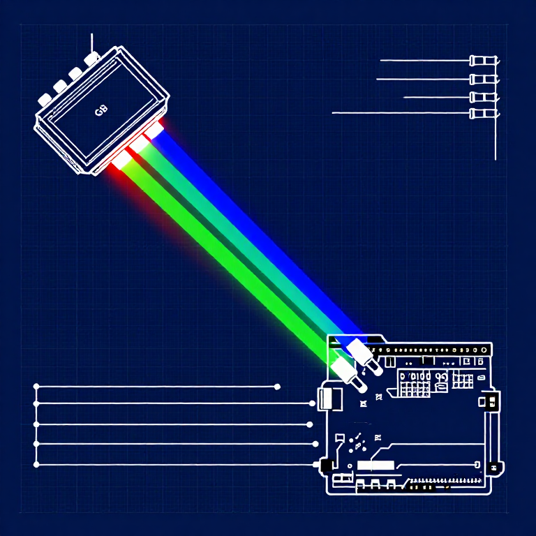
RGB LED Pin Order (flat edge facing you): Red, Ground (longest pin), Green, Blue.

2

Hardware Hookup

Wiring Instructions

  1. Place the RGB LED in the breadboard. Identify pins from the flattened edge: Red, GND (longest), Green, Blue.
  2. Connect the GND pin (longest, second from left) to the GND rail.
  3. Connect the Red pin through a 330Ω resistor to Arduino Pin 9.
  4. Connect the Green pin through a 330Ω resistor to Arduino Pin 10.
  5. Connect the Blue pin through a 330Ω resistor to Arduino Pin 11.

Pins 9, 10, and 11 are all PWM-capable (marked with ~ on the board).

3

Arduino Code

Open the Arduino IDE and upload the following sketch to your Arduino board.

rgb_led.inoarduino
/*
SparkFun Inventor's Kit
Example sketch 03 — RGB LED

Make an RGB LED display a rainbow of colors!

Hardware connections:
  RGB LED pins (from flattened edge): RED, COMMON, GREEN, BLUE
  RED -> 330 ohm resistor -> Pin 9
  COMMON -> GND
  GREEN -> 330 ohm resistor -> Pin 10
  BLUE -> 330 ohm resistor -> Pin 11

This code is completely free for any use.
*/

const int RED_PIN = 9;
const int GREEN_PIN = 10;
const int BLUE_PIN = 11;

int DISPLAY_TIME = 10;  // milliseconds

void setup()
{
  pinMode(RED_PIN, OUTPUT);
  pinMode(GREEN_PIN, OUTPUT);
  pinMode(BLUE_PIN, OUTPUT);
}

void loop()
{
  mainColors();
  showSpectrum();
}

void mainColors()
{
  // Off
  digitalWrite(RED_PIN, LOW);
  digitalWrite(GREEN_PIN, LOW);
  digitalWrite(BLUE_PIN, LOW);
  delay(1000);

  // Red
  digitalWrite(RED_PIN, HIGH);
  digitalWrite(GREEN_PIN, LOW);
  digitalWrite(BLUE_PIN, LOW);
  delay(1000);

  // Green
  digitalWrite(RED_PIN, LOW);
  digitalWrite(GREEN_PIN, HIGH);
  digitalWrite(BLUE_PIN, LOW);
  delay(1000);

  // Blue
  digitalWrite(RED_PIN, LOW);
  digitalWrite(GREEN_PIN, LOW);
  digitalWrite(BLUE_PIN, HIGH);
  delay(1000);

  // Yellow (red + green)
  digitalWrite(RED_PIN, HIGH);
  digitalWrite(GREEN_PIN, HIGH);
  digitalWrite(BLUE_PIN, LOW);
  delay(1000);

  // Cyan (green + blue)
  digitalWrite(RED_PIN, LOW);
  digitalWrite(GREEN_PIN, HIGH);
  digitalWrite(BLUE_PIN, HIGH);
  delay(1000);

  // Purple (red + blue)
  digitalWrite(RED_PIN, HIGH);
  digitalWrite(GREEN_PIN, LOW);
  digitalWrite(BLUE_PIN, HIGH);
  delay(1000);

  // White (all on)
  digitalWrite(RED_PIN, HIGH);
  digitalWrite(GREEN_PIN, HIGH);
  digitalWrite(BLUE_PIN, HIGH);
  delay(1000);
}

void showSpectrum()
{
  int x;
  for (x = 0; x < 768; x++)
  {
    showRGB(x);
    delay(DISPLAY_TIME);
  }
}

void showRGB(int color)
{
  int redIntensity;
  int greenIntensity;
  int blueIntensity;

  if (color <= 255)
  {
    redIntensity = 255 - color;
    greenIntensity = color;
    blueIntensity = 0;
  }
  else if (color <= 511)
  {
    redIntensity = 0;
    greenIntensity = 255 - (color - 256);
    blueIntensity = (color - 256);
  }
  else
  {
    redIntensity = (color - 512);
    greenIntensity = 0;
    blueIntensity = 255 - (color - 512);
  }

  analogWrite(RED_PIN, redIntensity);
  analogWrite(GREEN_PIN, greenIntensity);
  analogWrite(BLUE_PIN, blueIntensity);
}
4

Test & Experiment

What You Should See

The LED cycles through 8 solid colors (off, red, green, blue, yellow, cyan, purple, white) for 1 second each, then smoothly fades through the entire color spectrum.

Troubleshooting

  • Incorrect colors: With four pins close together, it's easy to misplace one. Double-check each connection.
  • Red too bright: The red diode is often brighter. Try a higher-value resistor on the red pin, or reduce in code: analogWrite(RED_PIN, redIntensity/3).

Experiments to Try

  • Add a potentiometer to control which color is displayed.
  • Create your own color sequences — try a "sunrise" effect (dark red → orange → yellow → white).

Materiales

  • SparkFun Inventor's Kit - V3.2 - 1 kitNOK 999.20
    Ver
  • Arduino Uno R3 - 1 pieceMarcador de posición
    Ver
  • Breadboard - 1 pieceMarcador de posición
    Ver
  • RGB LED (Common Cathode) - 1 pieceMarcador de posición
    Ver
  • 330 Ohm Resistor - 3 piecessNOK 24.00
    Ver
  • Jumper Wires - 5 piecessNOK 39.20
    Ver

Herramientas requeridas

  • Computer with Arduino IDE

CC0 Dominio público

Este Blueprint se publica bajo CC0. Eres libre de copiar, modificar, distribuir y usar este trabajo para cualquier propósito, sin pedir permiso.

Apoya al Maker comprando productos a través de su Blueprint, donde gana una Comisión del Maker establecida por los vendedores, o crea una nueva iteración de este Blueprint e inclúyela como conexión en tu propio Blueprint para compartir ingresos.

Discusión

(0)

Iniciar sesión para unirte a la discusión

Cargando comentarios...