Push Buttons — SIK Circuit 5
Instrucciones
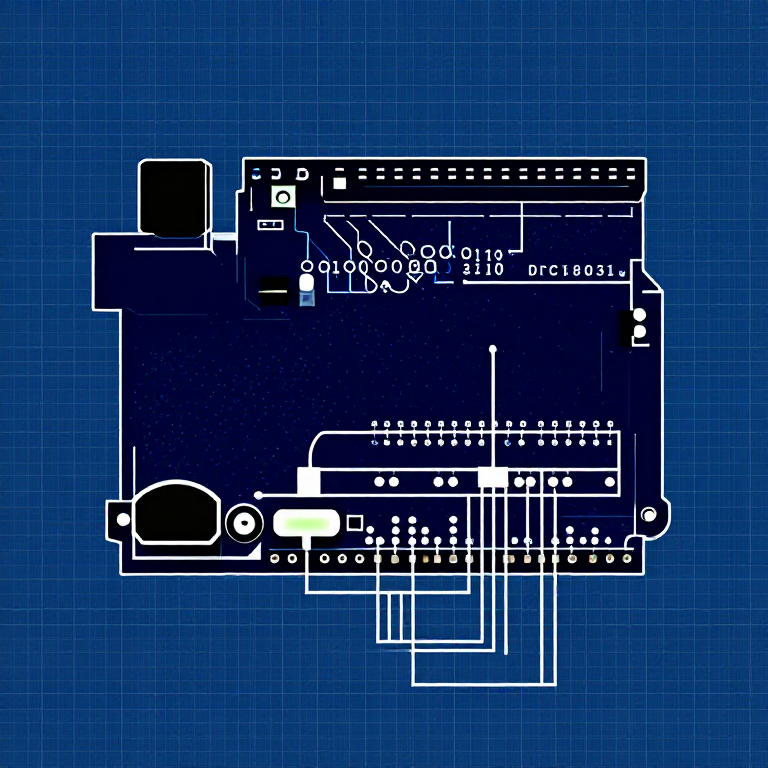
Parts & Introduction
Parts & Introduction
Push buttons are the simplest digital input. This experiment uses two buttons with an XOR logic gate: the LED turns on if you press either button, but turns off if you press both. You'll learn about digitalRead(), pull-up resistors, and boolean logic.
Parts Needed
- 1x Arduino Uno + USB cable
- 1x Breadboard
- 2x Push Buttons
- 1x LED (any color)
- 1x 330Ω Resistor
- 2x 10KΩ Resistors (pull-ups)
- 7x Jumper Wires
Materiales para este paso:
 SparkFun Inventors Kit - V3.21 kit
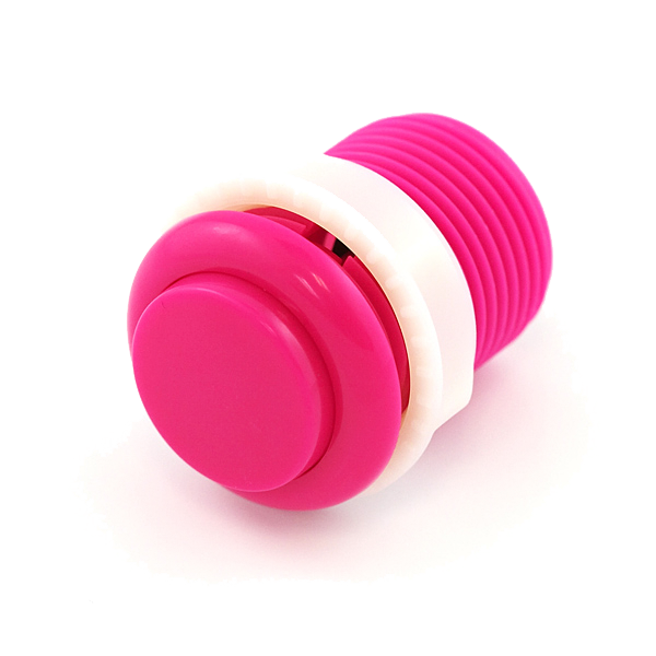 Push Button2 piezas
 330 Ohm Resistor1 pieza10K Ohm Resistor2 piezas
 Jumper Wires7 piezas
Herramientas necesarias:
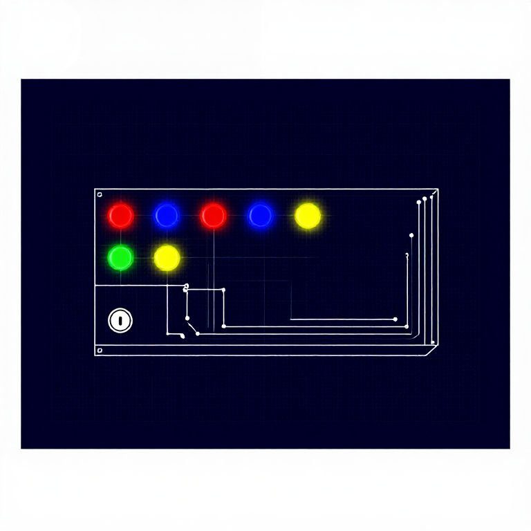
Hardware Hookup
Hardware Hookup
Wiring Instructions
- Place both push buttons across the center canyon of the breadboard.
- Button 1: Connect one pin to GND. Connect the opposite diagonal pin to Arduino Digital Pin 2. Add a 10K resistor between Pin 2 and 5V (pull-up).
- Button 2: Connect one pin to GND. Connect the opposite diagonal pin to Arduino Digital Pin 3. Add a 10K resistor between Pin 3 and 5V (pull-up).
- Connect LED positive leg to Digital Pin 13, negative leg through 330Ω resistor to GND.
Note: The pull-up resistors hold the input HIGH when the button is not pressed. Pressing the button connects the pin to GND (LOW).
Materiales para este paso:
Push Button2 piezas330 Ohm Resistor1 pieza10K Ohm Resistor2 piezasJumper Wires7 piezasArduino Code
Arduino Code
Open the Arduino IDE and upload the following sketch to your Arduino board.
Materiales para este paso:
Herramientas necesarias:
Test & Experiment
Test & Experiment
What You Should See
The LED turns on when you press either button individually. It turns off when you press both buttons simultaneously (XOR logic).
Troubleshooting
- Not responding: Push buttons are square — it's easy to put them in the wrong orientation. Try rotating 90°.
- LED always on or always off: Check the pull-up resistor connections. Without them, the input pin floats and reads random values.
Experiments to Try
- Change the logic to AND (both buttons required) or simple OR.
- Use the buttons to control an RGB LED — one button for color, one for brightness.
- Try using
INPUT_PULLUPmode to eliminate the external resistors.
Materiales
8- MX$1,826.00
- 2 piezasMX$21.00
- MX$44.00
- MX$44.00
- MX$72.00
Recommended for this build
Products makers often use with builds like this one.
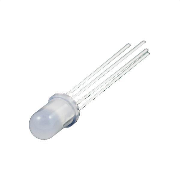 LED - RGB Diffused Common Cathode - 5mmFrequently used with this build's materials
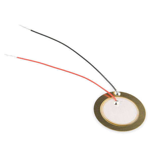 Piezo ElementUsed together and in similar builds
 1/4W Resistor Kit (600pcs, 30 Values)Frequently used with this build's materials
 Flex Sensor 2.2 InchFrequently used with this build's materials
 Basic 16x2 Character LCD - 5VUsed in similar builds
Related blueprints
Other builds that share materials, tools, or techniques with this one.

CC0 Dominio público
Este Blueprint se publica bajo CC0. Eres libre de copiar, modificar, distribuir y usar este trabajo para cualquier propósito, sin pedir permiso.
Apoya al Maker comprando productos a través de su Blueprint, donde gana una Comisión del Maker establecida por los vendedores, o crea una nueva iteración de este Blueprint e inclúyela como conexión en tu propio Blueprint para compartir ingresos.