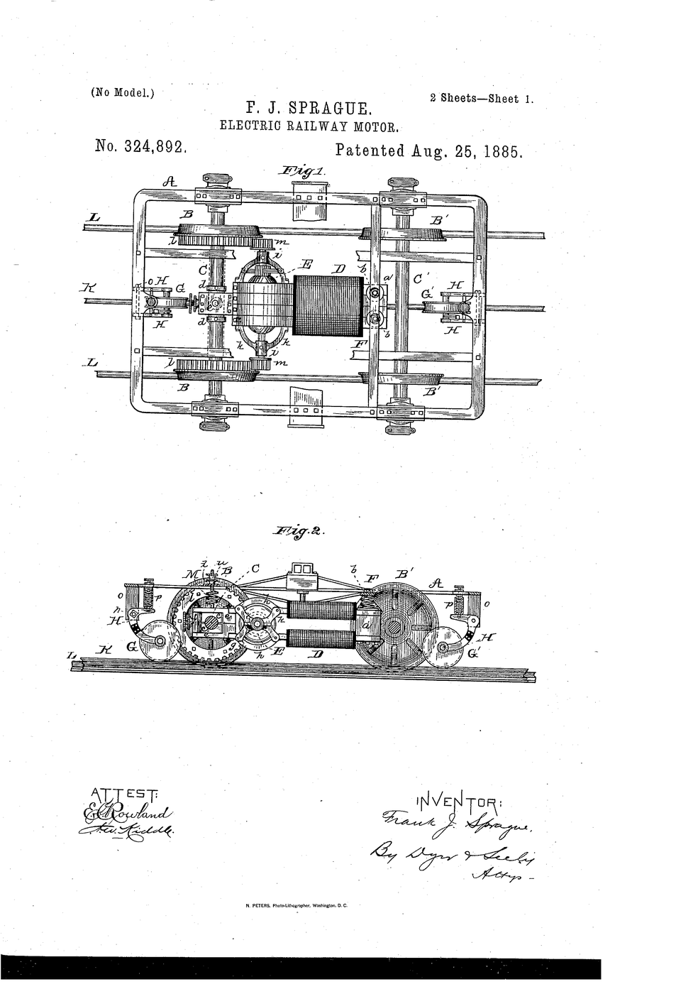


Electric Railway Motor
Putting an electric motor on a tram car sounds easy until you ask what to bolt it to. Bolt it to the car body and the springs let the body rise and fall — so the gap between the motor's pinion and the axle gear keeps changing, and the teeth grind, jam or skip. Bolt it hard to the axle instead and the mesh is perfect, but now the motor's whole dead weight is unsprung, hammering the rails and itself at every joint.
Sprague's answer is to do both at once. The field-magnet is sleeved onto the axle so one side of the motor rides with it and the gears stay permanently in mesh, while the other side is carried on flexible spring connections to the car body, taking most of the weight off the axle. The armature is supported directly on the field-magnet, so the working parts keep their alignment no matter what the suspension does.
Engineers call it the nose-suspended or "wheelbarrow" motor: half hung on the axle, half on springs.
US Patent 324,892, "ELECTRIC RAILWAY MOTOR", granted 25 August 1885 (filed 25 May 1885) to Frank J. Sprague of New York.
Instrucciones
Read the claim: sleeved on the axle, sprung to the body
Read the claim: sleeved on the axle, sprung to the body
Sprague claims the field-magnet sleeved upon the axle, the armature carried on the field-magnet, and spring connections to the vehicle. Note that it is deliberately attached to two things at once.
Build a car body on springs
Build a car body on springs
Cut a card body 200 mm long. Mount it on two compression springs at each end so it can bounce 10 mm up and down over its chassis.
Materiales para este paso:
 Láminas de cartón corrugado2 hojas
 Juego de muelles de compresión1 juego
Herramientas necesarias:
 Pistola de cola caliente
Fit a driven axle
Fit a driven axle
Run a dowel axle across the chassis in card bearings, with a wheel pressed on each end so it rolls freely.
Materiales para este paso:
 Varilla de madera (tarugo)1 pieza
 Motorreductor de corriente continua de 6 V (4 unidades con ruedas)1 juego
Wire the motor to a battery
Wire the motor to a battery
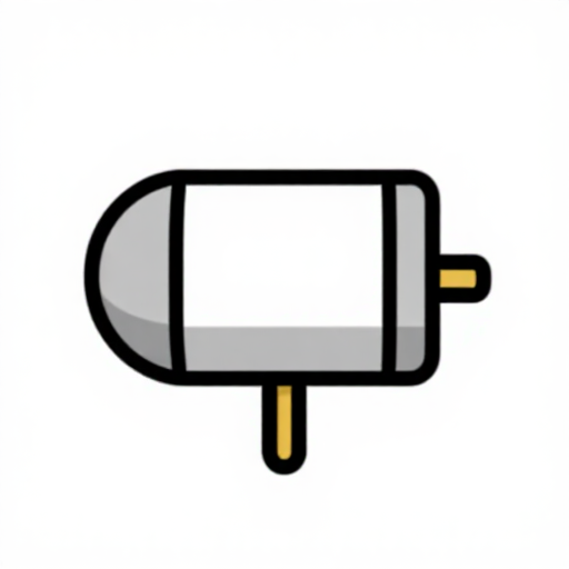
Clip the gear motor to the battery holder and check which way it turns. Keep the leads long and slack — they must not restrain the motor.
Herramientas necesarias:
 Portapilas
 Cables de prueba con pinzas de cocodrilo
Mounting A — bolt the motor to the body
Mounting A — bolt the motor to the body
Glue the motor rigidly to the sprung body, its pinion just meeting a wheel on the axle. Run it: it drives.
Herramientas necesarias:
Pistola de cola calienteNow push the body down while it runs
Now push the body down while it runs
Press the body down 10 mm as it drives. The pinion jams hard into the wheel; lift the body and it loses contact and spins free. The drive fails exactly when the track is rough.
Mounting B — clamp the motor to the axle
Mounting B — clamp the motor to the axle
Free the motor from the body and strap it to the axle so it rides with it. Run it: the mesh is now perfect however the body moves.
Herramientas necesarias:
 Cinta de carrocero
Weigh what the axle now carries
Weigh what the axle now carries
Lift the chassis by the axle and feel the load. All the motor's weight is unsprung — it sits below the springs and follows every bump directly.
Run it over a rough track
Run it over a rough track
Lay a row of cardboard strips as sleepers and run the car across. Watch the motor slam up and down with the axle — that shock goes into the rails and into the motor's own bearings.
Materiales para este paso:
Láminas de cartón corrugado1 hojaMounting C — Sprague's split
Mounting C — Sprague's split
Let the motor rest on the axle at one side as before, but now support its far end on a spring up to the car body. It hangs from two things at once, like a wheelbarrow.
Materiales para este paso:
Juego de muelles de compresión1 juegoTest the mesh again
Test the mesh again
Run it and press the body down. The gears stay meshed — because the motor's driving end never leaves the axle it drives. Mounting A's failure is gone.
Test the weight again
Test the weight again
Lift by the axle. It is noticeably lighter than in step 8 — the spring is carrying part of the motor. Roughly half the dead weight has moved above the suspension.
Run the rough track once more
Run the rough track once more
Cross the sleepers again. Less hammering, no gear skipping. One mounting solved both problems — write down why neither A nor B could.
History & Context — the mounting that electrified the streets
History & Context — the mounting that electrified the streets
The patent. US 324,892, "ELECTRIC RAILWAY MOTOR", granted 25 August 1885 to Frank J. Sprague of New York, filed 25 May 1885. The specification puts the field-magnet sleeved upon an axle of the vehicle with the armature supported on the field-magnet, uses flexible spring connections between motor and car body to keep the motor's parts in alignment regardless of suspension movement, and takes the drive from the armature shaft to the wheels through cog or friction gearing — relieving the axle of the motor's dead weight while preserving consistent engagement.
The problem is a conflict, and the answer is to stop choosing. Rigid to the body gives you light unsprung weight and a gear mesh that varies with every bump (steps 5-6). Rigid to the axle gives you a perfect mesh and a motor that rides unsprung, pounding the track and shaking itself apart (steps 7-9). Sprague's mounting takes the mesh from the axle and the weight from the springs, and it costs nothing but a bearing and a spring. Design problems that look like a trade-off are sometimes just two requirements attached to the wrong parts.
Unsprung weight is the quiet villain here. Anything below the springs must be accelerated bodily by every irregularity in the rail, so it both damages the track and is damaged by it. Halving it roughly halves those forces — the same reasoning that makes lightweight wheels and hubs matter on a bicycle or a car today.
What it enabled. Sprague had worked briefly for Edison before setting up on his own, and in 1888 equipped the Richmond Union Passenger Railway in Virginia — a full-sized, hilly, forty-car electric street railway that worked reliably in daily service. That installation is what convinced the world that electric traction was practical, and cities replaced horse cars at remarkable speed over the following decade. Sprague went on to develop multiple-unit control in 1897, letting one driver command motors distributed along a whole train, which is what made electric metros and suburban trains possible.
Where it sits. Nose-suspended traction motors, mounted on exactly this principle, drove trams, metro stock and locomotives throughout the twentieth century and remain in service. Modern high-speed designs go further and put nearly the whole motor on the sprung bogie frame, driving through a flexible coupling — chasing unsprung weight even harder, for the same reason Sprague hung half his motor on a spring in 1885.
Materiales
4- 3 hojasMarcador de posición
- Marcador de posición
- 1 piezaMarcador de posición
- Marcador de posición
Herramientas requeridas
4- Marcador de posición
- 14 vendors sell this, none ship to you yetMarcador de posición
- Marcador de posición
- Marcador de posición
Materiales de Blueprints conectados

Blueprints relacionados
Estos blueprints comparten conocimiento — técnicas, materiales o principios
CC0 Dominio público
Este Blueprint se publica bajo CC0. Eres libre de copiar, modificar, distribuir y usar este trabajo para cualquier propósito, sin pedir permiso.
Apoya al Maker comprando productos a través de su Blueprint, donde gana una Comisión del Maker establecida por los vendedores, o crea una nueva iteración de este Blueprint e inclúyela como conexión en tu propio Blueprint para compartir ingresos.