ARTE
BELLEZA Y BIENESTAR
ARTESANÍA
CULTURA E HISTORIA
ENTRETENIMIENTO
MEDIO AMBIENTE
COMIDA Y BEBIDAS
INGENIERÍA INVERSA
CIENCIAS
DEPORTES
TECNOLOGÍA
TECNOLOGÍA VESTIBLE
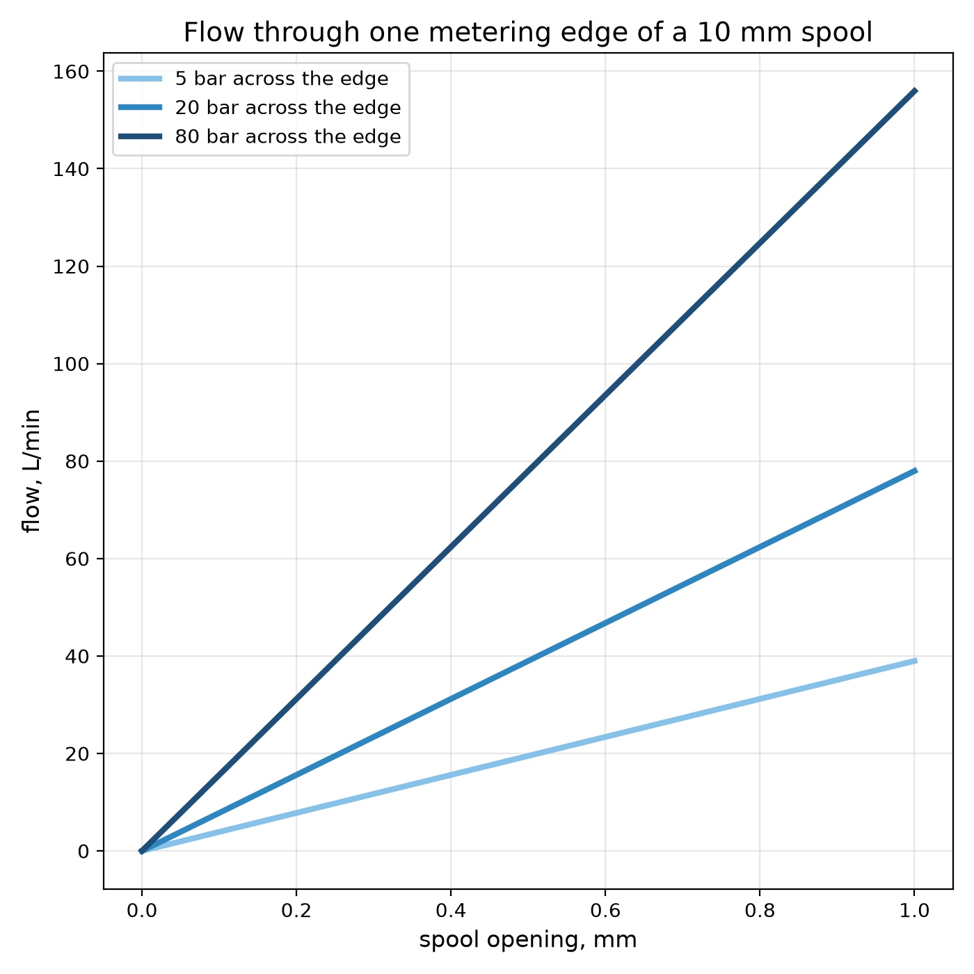
Youblob (generated from this blueprint's notebook) · CC0

The Spool Valve: Steering Oil With a Sliding Rod
A pump makes flow and a cylinder makes force. Between them sits the valve that decides where the oil goes: to one end of the cylinder, to the other, or back to the tank. In almost every hydraulic machine that valve is a **spool**: a ground steel rod with raised lands, sliding in a bore with five ports — pressure, tank, two work ports, and a second tank.
Slide the spool one way and pressure goes to port A while B drains; slide it the other way and the roles swap; centre it and the ports are blocked or joined, depending on the spool's centre. The edges of the lands are orifices, so the spool also meters how fast.
This rung works out the metering, the choice between open and closed centre, and builds a transparent spool valve that shows the oil paths in coloured water.
Intermedio
About 4 hours
Instrucciones
1
1
Metering edges and the centre condition
Metering edges and the centre condition
Cargando el cuaderno de Jupyter…
2
2
Each land edge is a throttle
Each land edge is a throttle
The spool meters flow the way any restriction does. The embedded blueprint shows how flow through a restriction depends on its area and the pressure across it.
3
3
Build a clear spool valve
Build a clear spool valve
Take 150 mm of clear acrylic tube with a smooth 20 mm bore. Drill five 6 mm holes in a line along one side, 20 mm apart, and glue a hose barb over each: from one end, **T**, **A**, **P**, **B**, **T**.
3D-print a spool: a 10 mm shaft carrying three lands, each 12 mm long with an O-ring groove, spaced so that when the spool is centred the middle land exactly covers **P** and the outer lands cover **A** and **B**. Fit O-rings sized to seal lightly in the bore. A handle on one end, a stop on the other.
Connect **P** to a garden hose through a ball valve, the two **T** ports to a bucket, and **A** and **B** to the two ports of the double-acting cylinder, or to two clear tubes standing up so you can see which one fills.
Materiales para este paso:
 Tubo acrílico (transparente)1 pieza
 Surtido de accesorios para tubo de PVC1 pieza
 Surtido de juntas tóricas1 pieza
 Tubo de silicona2 metros
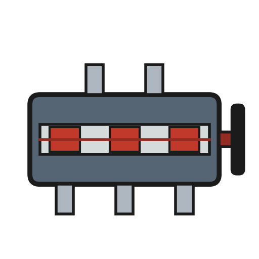 Válvula direccional1 pieza
Herramientas necesarias:
 Impresora 3D de filamento (FDM)
 Filamento PETG
 Taladro inalámbrico
 Juego de brocas
 Calibre digital de 6 pulgadas
 Pistola de cola caliente
 Cubo
Cubo4
4
The three positions
The three positions
Espacio de trabajo Blockly
Loading Blockly workspace...
5
5
Run it with coloured water
Run it with coloured water
Add food colouring to a bucket feeding a small submersible pump, or tint the hose supply with a dye injector, so the flow shows in the clear bore.
Centre the spool and open the supply: nothing moves, and the supply hose stiffens — that is a closed centre. Slide the spool slowly one way: first a thread of colour as the edge just cracks open, then a full stream into **A** while **B** drains to **T**. Slide it the other way and watch the paths swap.
Then turn the middle land down on a second printed spool so that, centred, it leaves a gap round **P**: now the supply runs straight through to **T** at the centre. That is an open centre.
Materiales para este paso:
 Colorante alimentario (tinte para visualizar el flujo)1 pieza
 Agua20 litros
Herramientas necesarias:
 Bomba de agua sumergible
 Cronómetro
6
6
A valve that will not control the load
A valve that will not control the load
Directional valve faults, in the order to check them.
Flow
Loading...
7
7
Context and honest limits
Context and honest limits
Spool valves go back to the steam age — slide valves on engines, piston valves on locomotives — and became the standard directional valve of oil hydraulics. Their symbols and port letters (P, T, A, B) are now standardised, so a circuit diagram from any maker reads the same way.
**Honest limits.** A spool always leaks a little through its clearance, so it cannot hold a load for long; a check valve does that. Flow through the edges also pushes on the spool (flow forces), which is why large valves are moved by pilot pressure rather than by hand. The printed model with O-rings shows the paths, not the metering: real spools seal by a micrometre clearance, not by rubber.
Materiales
7- 1 piezaMarcador de posición
- Marcador de posición
- 1 piezaMarcador de posición
- 2 metrosMarcador de posición
- 1 piezaMarcador de posición
- Marcador de posición
- 20 litrosMarcador de posición
Herramientas requeridas
9- Marcador de posición
- Marcador de posición
- 1 vendor sell this, none ship to you yetMarcador de posición
- Marcador de posición
- Marcador de posición
- Marcador de posición
- Marcador de posición
- Marcador de posición
- Marcador de posición
Blueprints relacionados
Estos blueprints comparten conocimiento — técnicas, materiales o principios
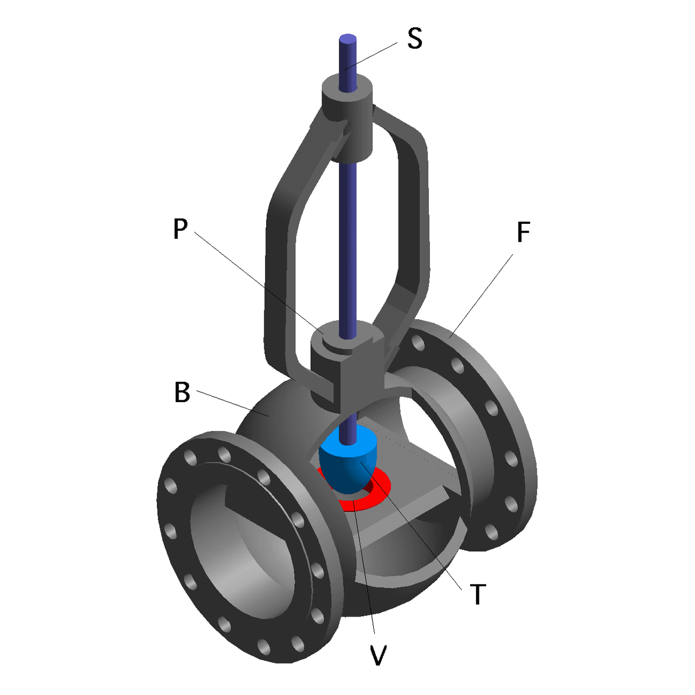
Throttling: Letting Some of It Past
por Emma
Mecánica
35
0
0
0
0
0
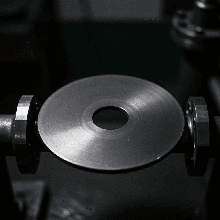
Orifice Plate Meter
por Emma
TECNOLOGÍA
47
0
0
0
0
0
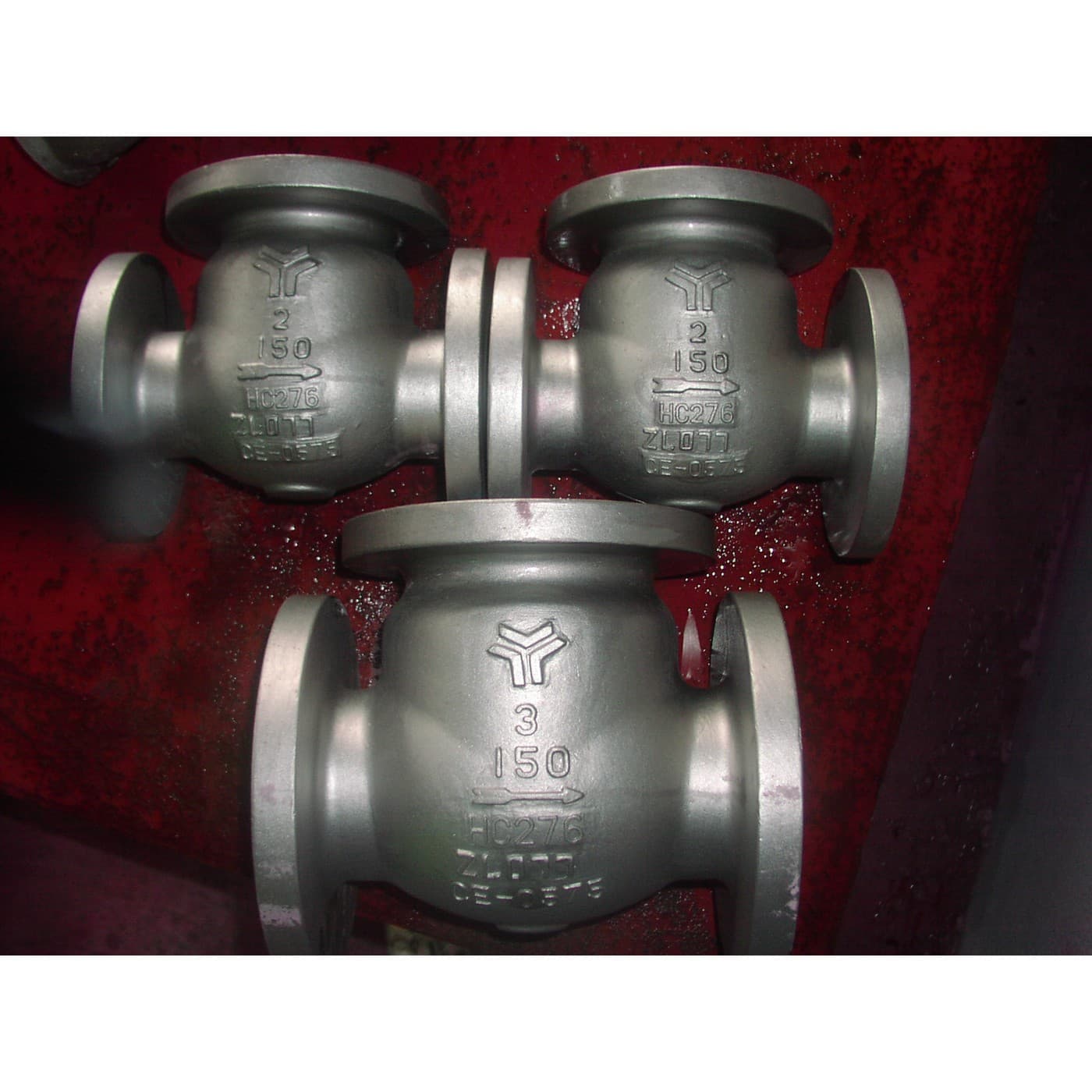
One Way Only: The Check Valve and the Bang It Makes
por Martin
Herramientas
40
0
0
0
0
0
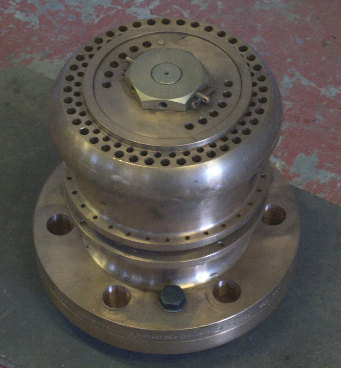
Safety Relief Valve
por Penny
TECNOLOGÍA
43
0
0
0
0
0
O-Ring Seal
por Mary
Trabajo en Metal
52
0
0
0
0
0
Hydraulic Accumulator
por Emma
Trabajo en Metal
36
0
0
0
1
0
CC0 Dominio público
Este Blueprint se publica bajo CC0. Eres libre de copiar, modificar, distribuir y usar este trabajo para cualquier propósito, sin pedir permiso.
Apoya al Maker comprando productos a través de su Blueprint, donde gana una Comisión del Maker establecida por los vendedores, o crea una nueva iteración de este Blueprint e inclúyela como conexión en tu propio Blueprint para compartir ingresos.