

The Wright Brothers' Wind Tunnel
Instrucciones
Reproduce the discrepancy that started it
Reproduce the discrepancy that started it
Before building the instrument, feel the problem that justified it.
- Take the lift figures you tabulated from the whirling arm, and use them to predict the lift of a model wing at a chosen speed and angle.
- Now measure that same wing directly, held in a steady airflow, using a spring scale.
- Compare prediction with measurement.
They will not agree, and the gap is the whole subject. A whirling arm measures a surface flying through its own wake; a straight tunnel measures it in clean air. Neither is lying, but they answer slightly different questions, and a coefficient carried from one to the other is being used outside the conditions that produced it.
The Wrights hit exactly this in a more brutal form: their glider generated about a third of the predicted lift. Two explanations were available — our building is bad, or the data is bad. Almost everyone in history picks the first, because the second requires believing you know better than the published authority.
They eventually traced part of the error to Lilienthal’s Smeaton coefficient, a constant relating air pressure to velocity that had been in use since the eighteenth century and was roughly 40 percent too high. It had been wrong for over a century and everyone had simply kept using it.Materiales para este paso:
 Papel milimetrado1 pad
Herramientas necesarias:
 Dinamómetro de muelle
 Transportador de ángulos
 Calibre digital de 6 pulgadas
 Anemómetro de mano
 Gafas de seguridad transparentes
Build the tunnel box and straighten the flow
Build the tunnel box and straighten the flow
A wind tunnel is easy to build and hard to build WELL, and the difference is entirely in the flow quality.
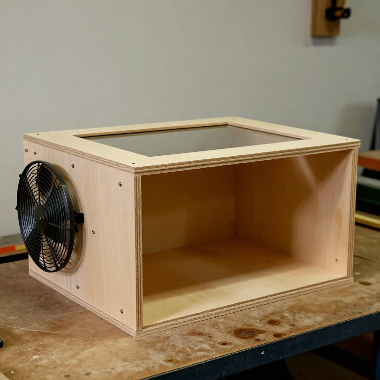
- Make an open-ended box roughly 1.5 m long with a square section of about 400 mm, from plywood, with a clear window in the top for observation.
- Fit a fan at the inlet end.
- Immediately downstream of the fan, install a flow straightener: a honeycomb of drinking straws or thin card tubes filling the whole section, at least 100 mm deep.
- Downstream of that, fit one or two fine mesh screens.
- Leave a working section of clear, unobstructed length before the test position.
The straightener and screens are not optional refinements — they are what makes the readings mean anything. A bare fan produces a swirling, turbulent corkscrew of air. The honeycomb kills the swirl by forcing every particle to travel parallel to the tube it is in; the screens break up the large eddies into small ones that decay quickly.
Test the result with an incense stick: the smoke should travel in a straight ribbon through the working section. If it wanders or spirals, add depth to the honeycomb or another screen. Do not proceed until the smoke is straight, because every number you take afterwards inherits the quality of this airflow.Materiales para este paso:
 Contrachapado de abedul con acabado UV1 hoja
 Pajitas (enderezador de flujo)200 piezas
 Malla fina1 m
 Cola de carpintero1 botella
 Lámina de acrílico1 hoja
Herramientas necesarias:
 Sierra de cinta de sobremesa
 Taladro de columna
 Gato de tornillo en C
 Escuadra combinadaCalibre digital de 6 pulgadas
 Varillas de incienso para visualizar el humo
 Ventilador de caja (velocidad variable)Gafas de seguridad transparentes
Verify the airspeed is uniform across the section
Verify the airspeed is uniform across the section
An instrument you have not calibrated is a decoration.
- Divide the working section into a 3 × 3 grid of measuring points.
- Measure airspeed at each with an anemometer, or with a pitot tube and manometer.
- Map the results and compute the spread between fastest and slowest.
- Adjust the straightener, screens or fan mounting until the spread is small — within a few percent across the centre.
If the flow is faster on one side than the other, a wing spanning the section is being tested at two different speeds at once, and its measured lift is a meaningless average. The Wrights understood this and kept their test surfaces small relative to the tunnel for the same reason.
See the pitot tube blueprint already in this catalogue for how to measure the speed properly — the difference between total and static pressure, and why the static port must be flush and burr-free. It is the same instrument that measures airspeed on aircraft today.Materiales para este paso:
Papel milimetrado1 padHerramientas necesarias:
Anemómetro de manoCalibre digital de 6 pulgadasEscuadra combinadaVarillas de incienso para visualizar el humoGafas de seguridad transparentesBuild the two balances that made it a measuring instrument
Build the two balances that made it a measuring instrument
This is the actual invention. The box moves air; the balances turn air into numbers.
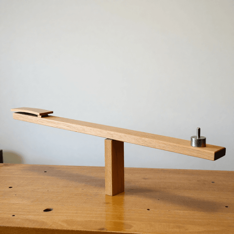
- Build the lift balance: a light frame carrying the test aerofoil, pivoted so that lift rotates it against a known restoring force, with a pointer reading against a scale.
- Build the drag balance separately, arranged so it responds to force along the flow and not across it.
- Make both from thin steel strip and wire — stiff in the direction being measured, compliant elsewhere.
- Calibrate each by hanging known small weights and marking the scale.
The Wrights’ genuine cleverness was that their balances did not measure force in pounds at all — they measured the RATIO of lift to drag directly, mechanically. A ratio cancels out the air density, the exact airspeed and the Smeaton coefficient — every one of the constants that had corrupted everyone else’s data. They made the instrument immune to the error that had wrecked the field.
That is a general and very powerful design move: when a constant in your calculation is untrustworthy, build the apparatus so the constant cancels. It is worth more than any amount of careful arithmetic with a bad number.
They built them from hacksaw blades and bicycle spoke wire, in a bicycle shop, in a few weeks. The sophistication is entirely in the arrangement, not the materials — which is exactly why it is reproducible on a modern bench.Materiales para este paso:
 Fleje de acero (acero para muelles, fino)1 pieza
 Cuerda de piano1 coil
 Tubo de latón de 9,5 mm de diámetro exterior1 pieza
 Juego de pesas de calibración1 juego
Herramientas necesarias:
 Juego de limas
 Tornillo de bancoTaladro de columnaCalibre digital de 6 pulgadas
 MicrómetroTransportador de ángulosGafas de seguridad transparentes
Test a series of aerofoils and find what actually matters
Test a series of aerofoils and find what actually matters
Now do what they did: vary one parameter at a time across many shapes.
- Cut a family of test aerofoils of equal area but differing aspect ratio — long and narrow through to short and wide.
- Run each through the angle range and record lift and drag.
- Then cut a second family with the same planform but differing camber, and repeat.
- Plot lift-to-drag ratio for both families.
The long, narrow wing beats the short, wide one decisively, at equal area. That is aspect ratio, and it was the single most valuable thing the tunnel told them. The reason is the wingtip: air spills from the high-pressure underside to the low-pressure top, rolling into a vortex that produces drag and no lift. A long thin wing has the same two tips but far more span doing useful work, so the penalty is spread thinner.
Look at where this rule leads and it is visible everywhere: gliders have enormous slender wings because efficiency is everything; fighters have stubby ones because roll rate and strength matter more. Albatrosses and swifts sit at opposite ends of the same trade. Once you can measure it, you can choose your position on it deliberately.Materiales para este paso:
 Plancha de madera de balsa3 hojas
 Listones de balsa1 manojoCola de carpintero1 botellaPapel milimetrado1 pad
Herramientas necesarias:
Sierra de cinta de sobremesa Lijadora de bandaCalibre digital de 6 pulgadasTransportador de ángulos
 Báscula digitalJuego de limasVarillas de incienso para visualizar el humoGafas de seguridad transparentes
Re-derive the wing you should have built
Re-derive the wing you should have built
Close the loop: use your own data to redesign the glider that started the problem.
- Take the aerofoil and aspect ratio that scored best in step 5.
- Compute the wing area needed to carry your model’s weight at the glide speed you measured earlier.
- Build that wing and fly it against the original.
- Compare glide ratios.
The redesigned wing should measurably outperform the one built from borrowed tables. That is the whole method in one line: measure, design from your own measurements, verify against the thing you replaced.
It is worth being precise about what the Wrights actually contributed, because it is usually described as ingenuity. It was not, particularly. It was refusing to trust an authority they could test, building an instrument whose design cancelled the error they suspected, and then re-deriving everything from scratch. The 1902 glider that came out of it flew hundreds of times; the 1903 Flyer was that glider with an engine and a propeller.
This blueprint deliberately ends with a measurement rather than a claim. If your redesigned wing does NOT beat the original, that is a real result and worth recording — check your balance calibration and your flow uniformity first, because those are where a tunnel most often lies to you.Materiales para este paso:
Plancha de madera de balsa2 hojasListones de balsa1 manojo Papel de seda para modelismo1 kit
 Barniz tensor para modelismo1 kitPapel milimetrado1 pad
Herramientas necesarias:
Sierra de cinta de sobremesaLijadora de bandaCalibre digital de 6 pulgadasTransportador de ángulosBáscula digital Teléfono móvil con vídeo a cámara lentaAnemómetro de manoGafas de seguridad transparentes
Materiales
14- 1 padMarcador de posición
- Marcador de posición
- 200 piezasMarcador de posición
- 1 mMarcador de posición
- 1 botellaMarcador de posición
- 1 hojaMarcador de posición
- Marcador de posición
- 1 coilMarcador de posición
- Marcador de posición
- Marcador de posición
- 5 hojasMarcador de posición
- 1 manojoMarcador de posición
- Marcador de posición
- Marcador de posición
Herramientas requeridas
17- Marcador de posición
- Marcador de posición
- Marcador de posición
- Marcador de posición
- Marcador de posición
- Marcador de posición
- Marcador de posición
- Marcador de posición
- Marcador de posición
- Marcador de posición
- Marcador de posición
- Marcador de posición
- Marcador de posición
- Marcador de posición
- 1 vendor sell this, none ship to you yetMarcador de posición
- Marcador de posición
- Marcador de posición
Blueprints relacionados
Estos blueprints comparten conocimiento — técnicas, materiales o principios

CC0 Dominio público
Este Blueprint se publica bajo CC0. Eres libre de copiar, modificar, distribuir y usar este trabajo para cualquier propósito, sin pedir permiso.
Apoya al Maker comprando productos a través de su Blueprint, donde gana una Comisión del Maker establecida por los vendedores, o crea una nueva iteración de este Blueprint e inclúyela como conexión en tu propio Blueprint para compartir ingresos.