Kerjasama
SENI
KECANTIKAN & KESEJAHTERAAN
KRAFTANGAN
BUDAYA & SEJARAH
HIBURAN
ALAM SEKITAR
MAKANAN & MINUMAN
KEJURUTERAAN TERBALIK
SAINS
SUKAN
TEKNOLOGI
BOLEH PAKAI
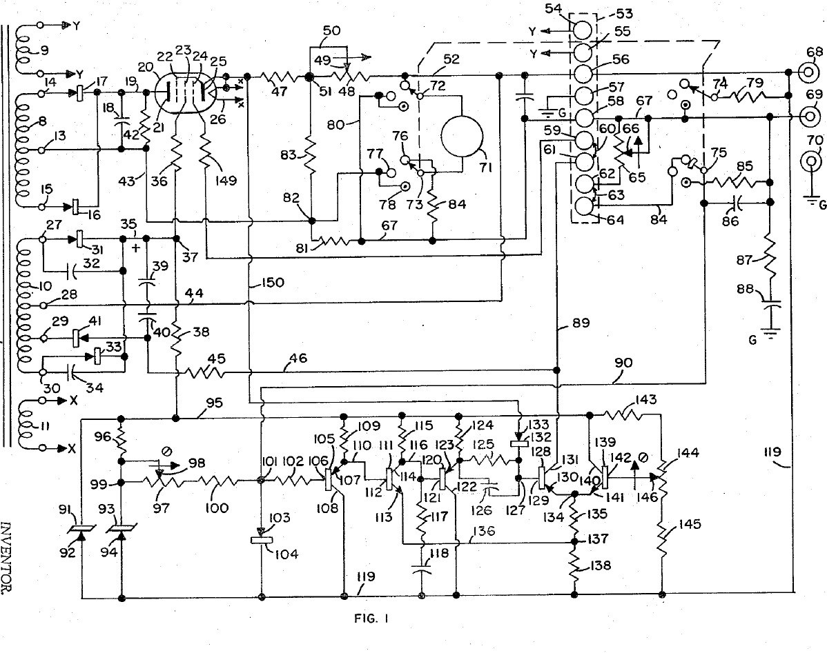


Bench Power Supply: Regulated, with Adjustable Current Limit and a Pentode Pass Tube (Gately, Forbro, US 3,243,690, 1966)
An adjustable bench supply that holds its output voltage steady and lets you set the most current it will deliver, so a circuit under test cannot be damaged. A pentode tube in series with the output is the regulator; a bridge with Zener references and a five-transistor amplifier keeps the output equal to the setting of one knob. A meter switch reads volts, amps, and the current limit, which can be set without disturbing the voltage.
Result: a regulated DC bench supply with adjustable current limiting.
Source: J. R. Gately (Forbro Design), US 3,243,690 (1966). Unknown: all component values and the output rating. Picture: the patent drawing.
Lanjutan
Unknown
Arahan
1
1
Wire the mains side
Wire the mains side
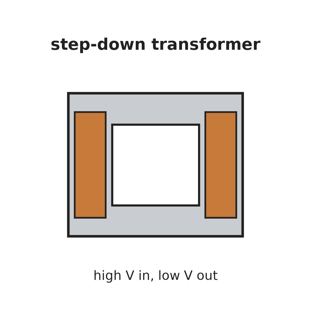
In a case, wire the power cord through a switch and a fuse to the primary of a transformer with four secondaries, and put a neon lamp across the primary to show the supply is on. One secondary (6.3 V) goes to two terminals for outside use, one heats the pentode, one is the main supply and one the bias supply. Ours: the case. Not given: the other winding voltages.
Bahan untuk langkah ini:
 Kotak kalis aluminium1 case
 Kord fleksibel berpalam1 keping
 Suis togol1 keping
 Fius1 keping
 Transformer Penurun1 four secondaries
 Lampu penunjuk neon1 keping
 Tiang pengikat2 6.3 V terminals
Alatan diperlukan:
 Gerimit tangan
 Set pemutar skru
2
2
Build the rectifiers
Build the rectifiers
Rectify the centre-tapped main winding with two rectifiers and smooth it with a capacitor. From the bias winding make two more supplies: one through two rectifiers with by-pass capacitors to a smoothing capacitor, for the pentode's screen and the reference circuit; the other through one rectifier and a capacitor, for the pentode's grid bias. Not given: the values.
Bahan untuk langkah ini:
 Diod5 rectifiers
 Kapasitor elektrolitik3 smoothing
 Kit Kapasitor1 by-pass
 Dawai Pateri1 as needed
Alatan diperlukan:
 Alat pematerian
3
3
Fit the pass tube and reference
Fit the pass tube and reference
Put the pentode in series with the positive output: plate to the main supply, cathode through two current-sensing resistors (one fixed, one adjustable) to the + output terminal; suppressor tied to the cathode, screen fed through a resistor. Build the reference: a Zener fed through a resistor feeds a second Zener at constant current, giving a fixed voltage. Against it set two resistors and the voltage-control variable resistor: the output voltage is proportional to that resistor's setting. Not given: the tube type and values.
Bahan untuk langkah ini:
 Tiub pentod1 series pass tube
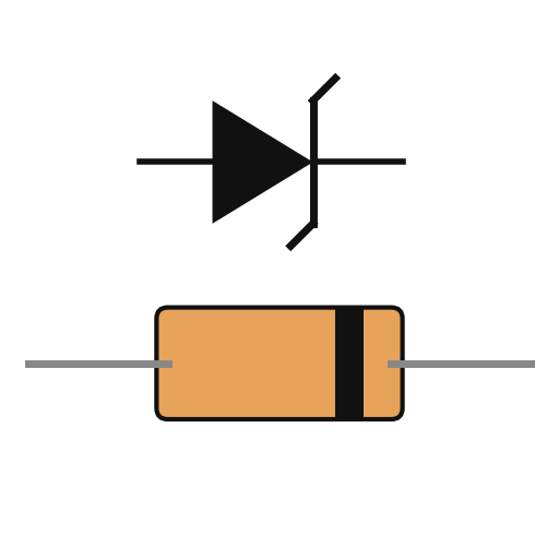 Diod Zener2 keping
 Rintangan1 set
 Reostat2 voltage control, current-limit rangeTiang pengikat2 output + and -Dawai Pateri1 as needed
Alatan diperlukan:
Alat pematerian4
4
Build the error amplifier and current limit
Build the error amplifier and current limit
Build a five-transistor amplifier that drives the pentode's grid to keep the bridge balanced: a PNP emitter follower, an NPN stage, a PNP emitter follower with a resistor-capacitor roll-off against oscillation, a PNP driver whose base resistor has a capacitor across it for quick response, and an NPN clamp whose base is set by a potentiometer. Feed the voltage across the current-sensing resistors to the driver's base through a diode: above the limit it takes over and turns the pentode down. Choose the fixed sensing resistor to limit at about 125 % of rated current, trim with the potentiometer, and use the adjustable one to set lower limits. Not given: the transistor types and values.
Bahan untuk langkah ini:
 Transistor PNP3 keping
 Transistor NPN2 kepingDiod1 keping
 Potensiometer1 kepingKit Kapasitor1 roll-off, speed-upRintangan1 setDawai Pateri1 as needed
Alatan diperlukan:
Alat pematerian5
5
Fit the meter and use it
Fit the meter and use it
Fit a meter with a four-pole, three-position switch. Position 1 reads output volts through a multiplier resistor; position 2 reads current across a shunt in the negative line; position 3 (spring-return) puts a load resistor across the output and swaps a fixed resistor for the voltage control, so you can turn the limit control until the current limits at the value you want, without touching the voltage setting. Release the switch and use the supply.
Bahan untuk langkah ini:
 Meter panel gegelung bergerak1 keping
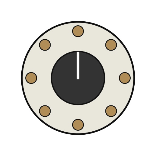 Suis putar1 4-pole, 3-positionRintangan1 multiplier, shunt, load resistors
 Bahan tidak diketahui1 terminal strip
Alatan diperlukan:
Alat pematerianSet pemutar skruBahan
21- 1 casePemegang Tempat
- 1 kepingPemegang Tempat
- Pemegang Tempat
- 1 kepingPemegang Tempat
- 1 four secondariesPemegang Tempat
- 1 kepingPemegang Tempat
- Pemegang Tempat
- 1 kepingPemegang Tempat
- 3 smoothingPemegang Tempat
- 1 roll-off, speed-upPemegang Tempat
- 3 as neededPemegang Tempat
- 1 series pass tubePemegang Tempat
- 2 kepingPemegang Tempat
- 1 multiplier, shunt, load resistorsPemegang Tempat
- 2 voltage control, current-limit rangePemegang Tempat
- 3 kepingPemegang Tempat
- 2 kepingPemegang Tempat
- Pemegang Tempat
- 1 kepingPemegang Tempat
- 1 4-pole, 3-positionPemegang Tempat
- 1 terminal stripPemegang Tempat
Blueprint ini membuat

CC0 Domain Awam
Blueprint ini dikeluarkan di bawah CC0. Anda bebas menyalin, mengubah, mengedar, dan menggunakan karya ini untuk sebarang tujuan, tanpa meminta kebenaran.
Sokong Pembuat dengan membeli produk melalui Blueprint mereka di mana mereka memperoleh Komisen Pembuat ditetapkan oleh Penjual, atau cipta iterasi baru Blueprint ini dan sertakan ia sebagai sambungan dalam Blueprint anda sendiri untuk berkongsi hasil.