SENI
KECANTIKAN & KESEJAHTERAAN
KRAFTANGAN
BUDAYA & SEJARAH
HIBURAN
ALAM SEKITAR
MAKANAN & MINUMAN
MASA DEPAN HIJAU
KEJURUTERAAN TERBALIK
SAINS
SUKAN
TEKNOLOGI
WEARABLES
Diterjemahkan
BLUEPRINT NFT

LED Berkedip LED — Projek Arduino Pertama Anda
Projek elektronik pertama yang klasik! Bina litar LED berkedip LED menggunakan Arduino, papan roti, perintang, dan satu LED. Sempurna untuk pemula mutlak — tiada kimpalan diperlukan.
Arahan
1
1
Kumpulkan Komponen Anda
Kumpulkan Komponen Anda
Kumpulkan semua komponen yang disenaraikan di bawah. Tiada keperluan menyolder — semuanya pasang ke papan roti.
Bahan untuk langkah ini:
 SparkFun Inventor's Kit - V3.21 kit
Arduino Uno R31 keping
5mm LED (any color)1 keping
 220 ohm Resistor (1/4W)1 keping
Breadboard1 keping
Jumper Wires (Male-to-Male)2 keping
USB-B Cable1 keping
Alatan diperlukan:
Computer with Arduino IDE
2
2
Skema Litar
Skema Litar
Aliran isyarat dari Arduino Pin 13 → perintang 220Ω (R1) → LED (D1) → GND. Perintang mengehadkan arus untuk melindungi LED.
Bahan untuk langkah ini:
Arduino Uno R31 keping
5mm LED (any color)1 keping
220 ohm Resistor (1/4W)1 keping3
3
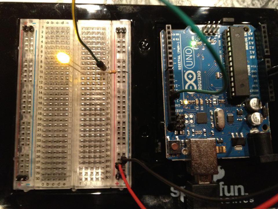
Wayarkan Dengan Sempurna
Wayarkan Dengan Sempurna
- Masukkan LED ke dalam papan roti — kaki panjang (anod +) dalam satu baris, kaki pendek (katod −) di baris seterusnya.
- Masukkan satu kaki perintang 220Ω ke dalam baris yang sama dengan katod LED. Kaki lain dalam baris berasingan.
- Wayar pelompat dari baris anod LED → Pin Arduino 13.
- Wayar pelompat dari baris bebas perintang → Arduino GND.
Bahan untuk langkah ini:
5mm LED (any color)1 keping
220 ohm Resistor (1/4W)1 kepingBreadboard1 keping
Jumper Wires (Male-to-Male)2 keping
4
4
Muat Naik Kod Blink
Muat Naik Kod Blink
Sambungkan Arduino melalui USB. Buka Arduino IDE, pilih Tools → Board → Arduino Uno, tampal kod, dan klik Upload.
blink.inoarduino
Bahan untuk langkah ini:
Arduino Uno R31 keping
USB-B Cable1 keping
Alatan diperlukan:
Computer with Arduino IDE
5
5
PCB Susun Atur (Rujukan)
PCB Susun Atur (Rujukan)
Ini menunjukkan litar sebagai susun atur PCB. Tidak diperlukan untuk projek ini — papan roti berfungsi dengan sempurna — tetapi menunjukkan bagaimana litar yang sama akan kelihatan jika dikilang sebagai papan sebenar.
6
6
Uji dan Eksperimen
Uji dan Eksperimen
LED berkelip? Tahniah! Anda baru sahaja memprogram perkakasan.
Penyelesaian masalah:
Eksperimen seterusnya:
Penyelesaian masalah:
- LED tidak menyala? Balikkan LED — kaki panjang ke arah Pin 13.
- LED tetap menyala? Periksa kod dimuat naik dengan berjaya.
- Tiada yang berlaku? Sahkan pendawaian sepadan dengan skematik dalam Langkah 2.
Eksperimen seterusnya:
- Ubah nilai
delay()untuk mengawal kecepatan berkelip - Tambah LED kedua pada Pin 12
- Gantikan dengan RGB LED (lihat Litar SIK 3)
Bahan
7- $105.00
- Pemegang Tempat
Jumlah anggaran
$105.00Related blueprints
Other builds that share materials, tools, or techniques with this one.

Using a Shift Register — SIK Circuit 14electronics/active
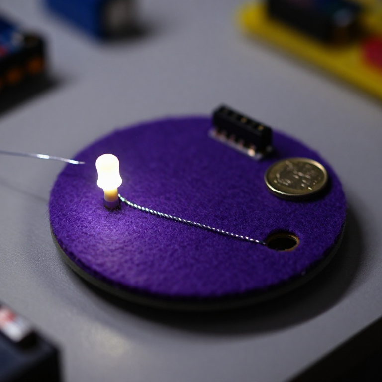
Blinking an LED with LilyPad Arduinoelectronics

Making Charcoal — The First Chemical Processmaterials

The Spinning Jenny — Multi-Spindle Yarn Productiontextiles

Starting Seeds Indoors — Raising Seedlings for a Head Start
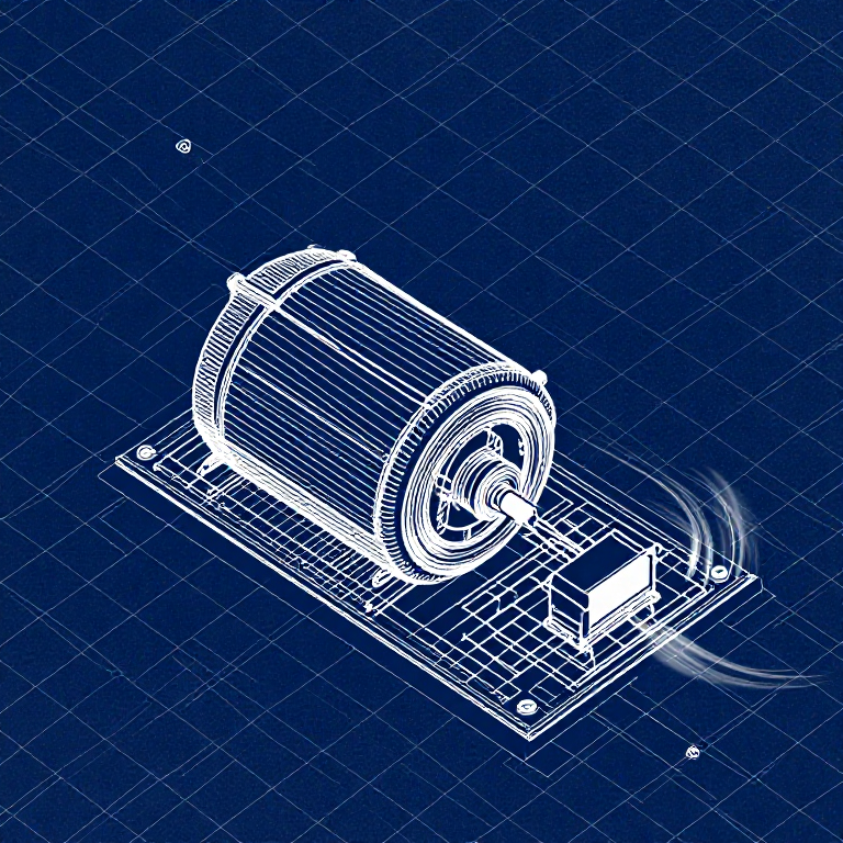
Driving a Motor — SIK Circuit 12electronics/electromech
CC0 Domain Awam
Blueprint ini dikeluarkan di bawah CC0. Anda bebas menyalin, mengubah, mengedar, dan menggunakan karya ini untuk sebarang tujuan, tanpa meminta kebenaran.
Sokong Pembuat dengan membeli produk melalui Blueprint mereka di mana mereka memperoleh Komisen Pembuat ditetapkan oleh Penjual, atau cipta iterasi baru Blueprint ini dan sertakan ia sebagai sambungan dalam Blueprint anda sendiri untuk berkongsi hasil.