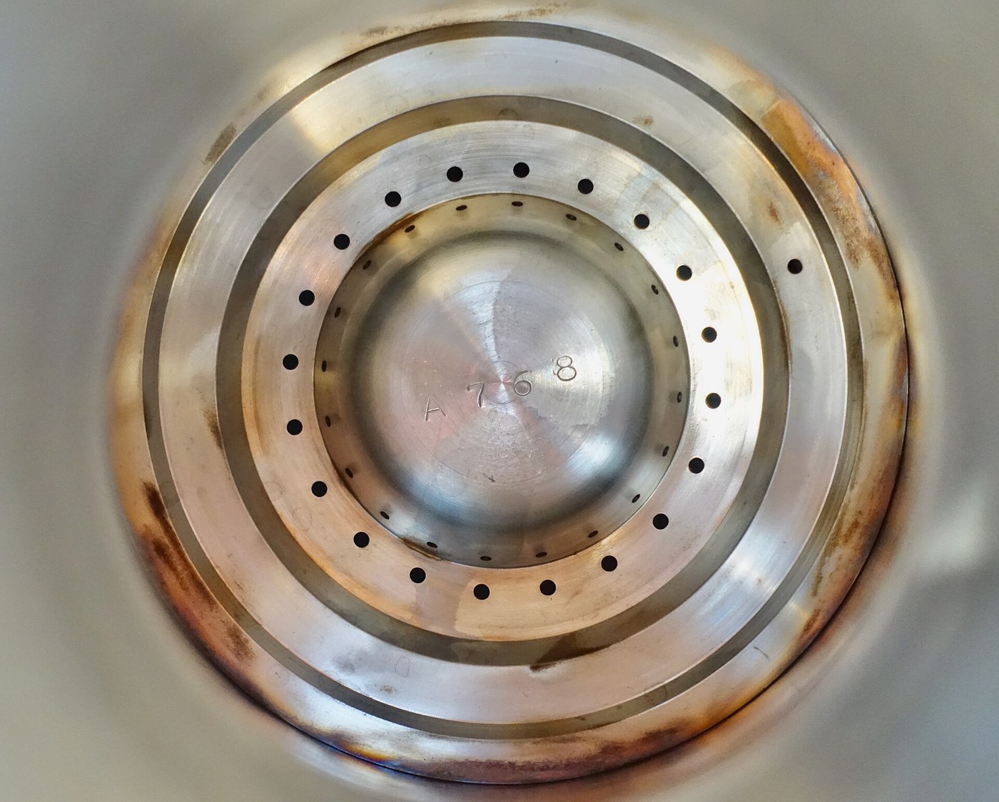


The Injector Plate and Combustion Instability
Arahan
Drill an impinging-jet pair and watch them collide
Drill an impinging-jet pair and watch them collide
Cold-flow with water first. Every injector development programme starts this way and so should yours.
- Drill two small holes in a plate, angled so their jets meet at a point a short distance downstream.
- Feed both from a pressurised water supply.
- Film the collision at high frame rate.
- Vary the impingement angle and the distance, and observe the resulting sheet.
Where the jets collide they form a flat fan-shaped sheet perpendicular to the plane of the two jets, and that sheet breaks up into droplets a short distance further on. The collision is doing the atomising — no swirl, no clever nozzle, just two streams hitting each other hard.
Feed one hole with water and the other with a dyed liquid and you can see the mixing directly. Impinging jets atomise and mix in the same act, which is precisely why the geometry is used.
Reverse-engineering note: the angle and the impingement distance are the design. Too shallow and the sheet is thick and coarse; too steep and the jets splash back toward the plate, which erodes it. Too far downstream and combustion begins before mixing completes, which is how you get hot streaks.Bahan untuk langkah ini:
 Plat kuprum1 keping
 Pewarna makanan (pewarna untuk penglihatan aliran)1 botol
Alatan diperlukan:
 Gerudi Tiang
 Ragum Pengisar 4 Inci
 Angkup Digital 6 Inci
 Mikrometer
 Telefon Pintar dengan Video Gerak Perlahan
 Tolok Tekanan
 Cermin Mata Keselamatan Jernih
Compare injector patterns and measure distribution
Compare injector patterns and measure distribution
Several geometries exist and each fails differently.
- Make three plates: like-on-like doublets (fuel hits fuel, oxidiser hits oxidiser), unlike doublets (fuel hits oxidiser), and a coaxial swirl element.
- Cold-flow each and catch the spray on a grid of small collection cups.
- Weigh the contents of each cup to map the distribution across the face.
- Compute the spread between the wettest and driest cups.
Unlike-impinging gives the best mixing and the worst uniformity; like-on-like gives even distribution and relies on the resulting sheets mixing further downstream. Neither is simply better.
The uniformity number matters more than it looks. A region receiving too much oxidiser burns hotter and locally, and since chamber walls are being cooled to survive at all, a hot streak is a burn-through waiting for its moment.
This is why injector faces are drilled in carefully worked-out patterns, why the outer ring is often deliberately fuel-rich to lay a cooler film against the wall, and why an injector is measured by cold-flow distribution before it ever meets fire.Bahan untuk langkah ini:
Plat kuprum2 keping Kertas Graf1 pad
Alatan diperlukan:
Gerudi TiangRagum Pengisar 4 InciAngkup Digital 6 InciMikrometer Penimbang DigitalTelefon Pintar dengan Video Gerak PerlahanTolok TekananCermin Mata Keselamatan Jernih
Set the pressure drop, and find out why it must be large
Set the pressure drop, and find out why it must be large
The injector deliberately wastes pressure, and the waste is the point.
- Measure flow rate against pressure drop across your injector plate.
- Now simulate a chamber pressure oscillation by pulsing the downstream pressure, and watch how much the flow rate varies.
- Repeat with a much larger pressure drop across the injector.
With a small pressure drop, chamber pressure fluctuations feed straight back into the propellant flow; with a large one, the flow barely notices. The injector is acting as a hydraulic resistance that DECOUPLES the feed system from the chamber.
That decoupling is the first line of defence against instability. If chamber pressure can modulate the flow, and the flow modulates the combustion, and the combustion drives the chamber pressure, you have a loop with gain — exactly the structure of the regenerative receiver in the radio batch, except that here oscillation destroys the hardware.
Typical designs spend 15 to 20 percent of chamber pressure across the injector. That is pressure the turbopump had to generate and that produces no thrust whatsoever — bought purely to break a feedback path. A cheap insurance premium against an expensive failure.Bahan untuk langkah ini:
Plat kuprum1 kepingKertas Graf1 padAlatan diperlukan:
Tolok TekananPenimbang Digital OsiloskopTelefon Pintar dengan Video Gerak Perlahan
 Pemampat udara 30 gelenCermin Mata Keselamatan Jernih
Find the chamber's acoustic modes before firing it
Find the chamber's acoustic modes before firing it
A combustion chamber is an organ pipe that happens to contain a fire.
- Take your chamber body, unfired, and excite it acoustically — a small speaker at one end, a microphone at the other.
- Sweep frequency and find the resonant peaks.
- Identify the longitudinal mode, and the tangential and radial modes, and note their frequencies.
- Compute the expected frequencies from chamber dimensions and the speed of sound in the hot gas.
The chamber has strong preferred frequencies determined purely by its dimensions, and the tangential modes are the dangerous ones. A tangential oscillation is a pressure wave running round the chamber circumference, and it sweeps across the injector face driving the flow in and out in step with itself.
Instability is not combustion going wrong — it is combustion going right, in time with an acoustic mode. Heat released at the moment of peak pressure adds energy to the wave; that is Rayleigh’s criterion, and it is the same condition that makes a singing flame or a Rijke tube work.
Remember to use the speed of sound in the HOT gas, which is two to three times the cold-air figure. A chamber that seems safely resonant at 800 Hz cold may be sitting at 2 kHz when running.Bahan untuk langkah ini:
 Tiub keluli 12 mm1 kepingKertas Graf1 pad
Alatan diperlukan:
OsiloskopTelefon Pintar dengan Video Gerak PerlahanAngkup Digital 6 InciMikrometer Termometer InframerahCermin Mata Keselamatan Jernih
Add baffles and acoustic cavities, and kill the mode
Add baffles and acoustic cavities, and kill the mode
The fix is geometric: make the chamber a shape the dangerous mode cannot fit inside.
- Fit radial baffles projecting from the injector face into the chamber, dividing it into sectors.
- Re-measure the acoustic modes.
- Add Helmholtz cavities around the injector periphery — small tuned volumes opening into the chamber.
- Measure again and compare the damping.
Baffles break the chamber into compartments too small to support the tangential mode at its original frequency, pushing it far higher where it is more heavily damped. The Helmholtz cavities absorb energy at a chosen frequency, exactly as a bass trap does in a room.
The F-1 story is worth knowing precisely because it is not a story about clever analysis. The team could not predict instability reliably, so they detonated small bombs inside running engines to provoke it, and measured how fast the chamber recovered. An engine that damped a deliberate disturbance within a few hundred milliseconds was declared stable, and the baffle design was iterated empirically until it did. The final F-1 injector has thirteen baffle compartments.
That is a legitimate engineering method and worth naming: when a phenomenon resists prediction, build the ability to PROVOKE it on demand and measure the recovery. It converts an unpredictable failure into a repeatable test.Bahan untuk langkah ini:
Plat kuprum1 kepingTiub keluli 12 mm1 keping Skru kepala silinder M58 keping
Alatan diperlukan:
Ragum Pengisar 4 InciGerudi Tiang Mesin kimpalan TIGAngkup Digital 6 InciOsiloskopTermometer Inframerah
 Sepana TorkCermin Mata Keselamatan Jernih
 Perisai Muka
Bahan
5- 5 kepingPemegang Tempat
- Pemegang Tempat
- 1 padPemegang Tempat
- 1 kepingPemegang Tempat
- 8 kepingPemegang Tempat
Alatan Diperlukan
14- Pemegang Tempat
- Pemegang Tempat
- Pemegang Tempat
- Pemegang Tempat
- Pemegang Tempat
- Pemegang Tempat
- Pemegang Tempat
- Pemegang Tempat
- Pemegang Tempat
- Pemegang Tempat
- Pemegang Tempat
- Pemegang Tempat
- Pemegang Tempat
- Pemegang Tempat
Blueprint berkaitan
Blueprint ini berkongsi pengetahuan — teknik, bahan atau prinsip

CC0 Domain Awam
Blueprint ini dikeluarkan di bawah CC0. Anda bebas menyalin, mengubah, mengedar, dan menggunakan karya ini untuk sebarang tujuan, tanpa meminta kebenaran.
Sokong Pembuat dengan membeli produk melalui Blueprint mereka di mana mereka memperoleh Komisen Pembuat ditetapkan oleh Penjual, atau cipta iterasi baru Blueprint ini dan sertakan ia sebagai sambungan dalam Blueprint anda sendiri untuk berkongsi hasil.