Kerjasama
SENI
KECANTIKAN & KESEJAHTERAAN
KRAFTANGAN
BUDAYA & SEJARAH
HIBURAN
ALAM SEKITAR
MAKANAN & MINUMAN
KEJURUTERAAN TERBALIK
SAINS
SUKAN
TEKNOLOGI
BOLEH PAKAI
Makro On-Chip: Cahaya Bernafas yang Disimpan dalam Memori Cip Anda Sendiri
English
Youblob (simulation output) · CC0

Ed

Dicipta oleh

Ed

29. September 2026FI
49
0
0
0
0

Makro On-Chip: Cahaya Bernafas yang Disimpan dalam Memori Cip Anda Sendiri

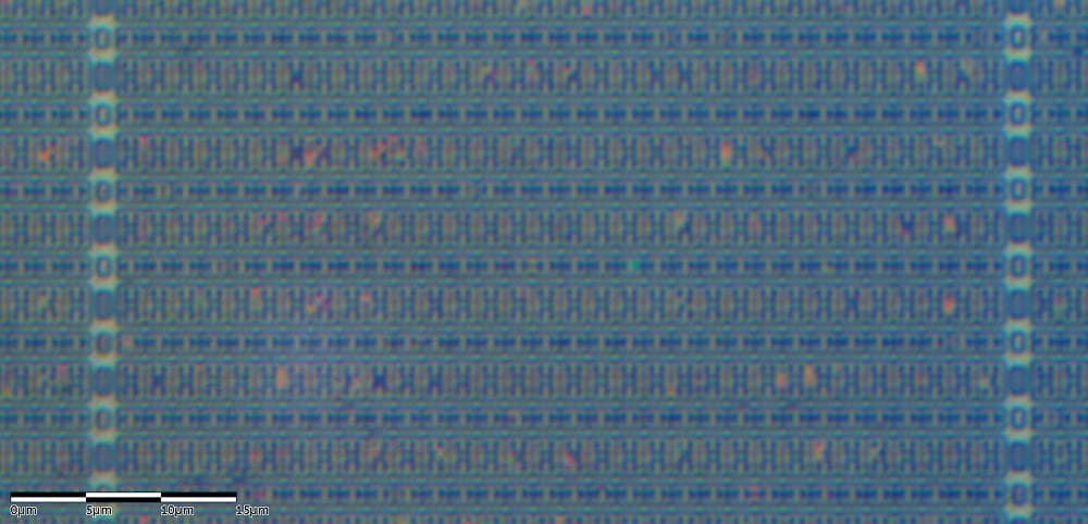
Templat wafer.space dilengkapi dengan dua makro SRAM dalam reka bentuk contohnya, masing-masing 512 bait, dan membiarkannya dimatikan. Makro ialah blok memori siap sedia daripada PDK: 4,096 sel memori statik, dilukis sekali dengan penyahkod alamat dan litar bacaannya, yang anda letakkan secara keseluruhan dan bukannya membina daripada get. Peringkat ini menghidupkan salah satunya. Pengdim PWM dari peringkat sebelumnya kini memainkan corak: sebuah mikropengawal menulis 256 bait ke dalam cip melalui pad-padnya, sekali sahaja, dan selepas itu cip membaca semula bait-bait tersebut dengan sendirinya, satu bait setiap langkah, sebagai kecerahan lampu yang bernafas perlahan-lahan. Teras dan testbench-nya dijalankan untuk cetak biru ini dengan Icarus Verilog 12.0, cocotb 2.1.0 dan model simulasi milik PDK bagi makro SRAM: output mengikuti jadual tersimpan selama 600 tempoh PWM. Gambar tersebut ialah output simulasi itu sendiri, satu bar setiap tempoh. Lakaran ESP32 yang memuatkan jadual itu telah disusun untuk cetak biru ini; belum ada cip untuk menjalankannya.
Lanjutan
Sebuah petang, serta cip

Arahan

1

Corak, masa dan saiznya

Memuatkan buku nota Jupyter…
2

Apa yang diwakili oleh setiap satu daripada 4,096 bit

Gambar rajah terbenam menunjukkan bagaimana satu bit memori statik mengekalkan dirinya: satu gelung dua penyongsang. Makro dalam anak tangga ini ialah 4,096 bit memori statik dalam satu tatasusunan.
3

Pin makro, dan tiga perkara yang dinyatakan oleh modelnya

gf180mcu_fd_ip_sram__sram512x8m8wm1 menyimpan 512 bait. Pinnya: CLK; A, alamat 9-bit; D, bait untuk ditulis; Q, bait yang dibaca. Ketiga-tiga kawalan semuanya aktif LOW. CEN pada 0 menghidupkan memori. GWEN pada 0 menjadikan tepi jam sebagai tulis, pada 1 sebagai baca. WEN ialah satu bit bagi setiap bit data, dan 0 membenarkan bit itu ditulis, jadi satu tulisan boleh mengubah sebahagian bit dalam bait dan membiarkan yang lain tidak berubah. Membaca model simulasi PDK menunjukkan tiga perkara yang patut diketahui. Pertama, memori hanya berfungsi selepas CEN beralih dari 1 ke 0; jika tidak, model mencetak "CEN is not reset, memory is not operational", jadi teras memegang CEN pada 1 semasa tetapan semula dan menurunkannya selepas itu. Kedua, bacaan memberikan mem[A] pada Q sejurus selepas tepi jam yang mensampel A, jadi data sedia satu kitaran jam kemudian. Ketiga, model bermula dengan setiap bait pada 0. Cip sebenar tidak: SRAM dihidupkan dengan memegang apa sahaja yang jatuh ke dalam setiap sel, jadi reka bentuk mesti menulis sebelum membaca. Contoh templat menetapkan CEN kepada 1, jadi dua makronya dimatikan. Fail pemasaannya memberikan tempoh jam minimum makro sebagai 6.6 ns pada sudut tipikal 5 V dan 18.3 ns pada sudut perlahan 3.0 V, 125 °C, kedua-duanya jauh dalam had 40 ns templat.
4

The core

src/chip_core.sv for the pattern player, with the template's port list unchanged plus one parameter, HOLD_LOG2. Input pad 0 enables, pad 1 selects LOAD mode, pad 2 is the write strobe; bidirectional pads 0 to 7 carry the byte, pad 8 the PWM. The LOAD and strobe pads are passed through two flip-flops before use, a synchroniser: they change whenever the outside world likes, not in step with the chip's clock, and a flip-flop caught mid-change can hover between 0 and 1 for a while. In play mode, each time HOLD_LOG2 periods have passed, the byte the SRAM has been reading becomes the new duty and the address moves on.
chip_core.svsystemverilog
// SPDX-License-Identifier: Apache-2.0
// Youblob silicon rung 5: the PWM dimmer plays a brightness pattern stored in the on-chip SRAM macro.
// Port list unchanged from wafer-space/gf180mcu-project-template src/chip_core.sv.

`default_nettype none

module chip_core #(
    parameter NUM_INPUT_PADS,
    parameter NUM_BIDIR_PADS,
    parameter NUM_ANALOG_PADS,
    parameter HOLD_LOG2 = 9        // each table entry lasts 2**HOLD_LOG2 PWM periods
    )(
    `ifdef USE_POWER_PINS
    inout  wire VDD,
    inout  wire VSS,
    `endif

    input  wire clk,       // clock
    input  wire rst_n,     // reset (active low)

    input  wire [NUM_INPUT_PADS-1:0] input_in,   // Input value
    output wire [NUM_INPUT_PADS-1:0] input_pu,   // Pull-up
    output wire [NUM_INPUT_PADS-1:0] input_pd,   // Pull-down

    input  wire [NUM_BIDIR_PADS-1:0] bidir_in,   // Input value
    output wire [NUM_BIDIR_PADS-1:0] bidir_out,  // Output value
    output wire [NUM_BIDIR_PADS-1:0] bidir_oe,   // Output enable
    output wire [NUM_BIDIR_PADS-1:0] bidir_cs,   // Input type (0=CMOS Buffer, 1=Schmitt Trigger)
    output wire [NUM_BIDIR_PADS-1:0] bidir_sl,   // Slew rate (0=fast, 1=slow)
    output wire [NUM_BIDIR_PADS-1:0] bidir_ie,   // Input enable
    output wire [NUM_BIDIR_PADS-1:0] bidir_pu,   // Pull-up
    output wire [NUM_BIDIR_PADS-1:0] bidir_pd,   // Pull-down

    inout  wire [NUM_ANALOG_PADS-1:0] analog  // Analog
);

    // Input pad 0: enable.  Input pad 1: LOAD mode.  Input pad 2: write strobe.
    // Bidir pads 0..7: the byte to store while loading.  Bidir pad 8: the PWM output.
    localparam DUTY_W = 8;
    localparam PWM_PAD = 8;

    assign input_pu = '0;
    assign input_pd = '0;
    assign bidir_oe = {{(NUM_BIDIR_PADS-DUTY_W){1'b1}}, {DUTY_W{1'b0}}};
    assign bidir_ie = ~bidir_oe;
    assign bidir_cs = {{(NUM_BIDIR_PADS-DUTY_W){1'b0}}, {DUTY_W{1'b1}}};
    assign bidir_sl = '0;
    assign bidir_pu = '0;
    assign bidir_pd = '0;

    wire enable = input_in[0];
    wire [DUTY_W-1:0] data_in = bidir_in[DUTY_W-1:0];

    // The mode and strobe pads change whenever the outside world likes, not in step with clk:
    // two flip-flops in a row (a synchroniser) before anything uses them.
    logic [1:0] load_s;
    logic [2:0] strobe_s;
    always_ff @(posedge clk) begin
        load_s   <= {load_s[0], input_in[1]};
        strobe_s <= {strobe_s[1:0], input_in[2]};
    end
    logic load_was;
    wire load        = load_s[1];
    wire load_start  = load & ~load_was;
    wire strobe_rise = strobe_s[1] & ~strobe_s[2];
    always_ff @(posedge clk) load_was <= load;

    // The SRAM wants its chip enable (CEN, active LOW) to go 1 -> 0 before it works:
    // hold it at 1 through reset, then 0.
    logic cen;
    always_ff @(posedge clk) cen <= !rst_n;

    // PWM counter and the "hold" counter that decides when to step to the next table entry.
    logic [DUTY_W-1:0] count;
    logic [HOLD_LOG2:0] hold;                   // one bit wider so HOLD_LOG2 = 0 still works
    wire period_end = (count == '1);
    localparam logic [HOLD_LOG2:0] HOLD_MASK = (1 << HOLD_LOG2) - 1;   // 0 when HOLD_LOG2 = 0
    wire step = period_end && ((hold & HOLD_MASK) == HOLD_MASK);

    logic [DUTY_W-1:0] addr;
    logic [DUTY_W-1:0] duty;
    wire  [DUTY_W-1:0] q;                       // SRAM read data: mem[addr], one clock after addr

    always_ff @(posedge clk) begin
        if (!rst_n) begin
            count <= '0;  hold <= '0;  addr <= '0;  duty <= '0;
        end else if (load) begin
            count <= '0;  hold <= '0;  duty <= '0;
            if (load_start)       addr <= '0;       // every load starts at entry 0
            else if (strobe_rise) addr <= addr + 1'b1;
        end else if (enable) begin
            count <= count + 1'b1;
            if (period_end) hold <= hold + 1'b1;
            if (step) begin
                duty <= q;                          // the entry that was being read
                addr <= addr + 1'b1;                // and move on to the next
            end
        end
    end

    `gf180mcu_xxx_ip_sram__sram512x8m8wm1 sram_0 (
        `ifdef USE_POWER_PINS
        .VDD  (VDD),
        .VSS  (VSS),
        `endif
        .CLK  (clk),
        .CEN  (cen),                                   // active low: 0 = on
        .GWEN (~(load && strobe_rise)),                // active low: 0 = write this clock
        .WEN  (8'b0),                                  // active low, per bit: write all eight
        .A    ({1'b0, addr}),                          // 256 of the 512 bytes
        .D    (data_in),
        .Q    (q)
    );

    logic pwm;
    always_ff @(posedge clk) begin
        if (!rst_n) pwm <= 1'b0;
        else        pwm <= enable && !load && (count < duty);
    end

    logic [NUM_BIDIR_PADS-1:0] out;
    always_comb begin
        out = '0;
        out[PWM_PAD] = pwm;
    end
    assign bidir_out = out;

    // Inputs this design does not read (keeps lint quiet, as the template does with _unused).
    logic _unused;
    assign _unused = &{1'b0, input_in[NUM_INPUT_PADS-1:3], bidir_in[NUM_BIDIR_PADS-1:DUTY_W], hold[HOLD_LOG2]};

endmodule

`default_nettype wire

Alatan diperlukan:

Komputer MejaKomputer Meja
5

The test

test_pattern.py builds the core with the PDK's SRAM model, gf180mcu_fd_ip_sram__sram512x8m8wm1.v, at the template's 25 MHz and with HOLD_LOG2 = 0 so the whole table plays in 256 periods. It loads the table through the pads the way the ESP32 will, then counts the high clocks in each of 600 PWM periods and requires them to follow the table from exactly one starting point. A second test loads again and checks the new pattern replaced the old.
test_pattern.pypython
# SPDX-License-Identifier: Apache-2.0
# cocotb testbench for the SRAM pattern player, with the PDK's own SRAM simulation model
# (gf180mcu_fd_ip_sram__sram512x8m8wm1, gf180mcuD, the commit the template pins).
import math
import os
from pathlib import Path

import cocotb
from cocotb.clock import Clock
from cocotb.triggers import ClockCycles, FallingEdge, RisingEdge
from cocotb_tools.runner import get_runner

PWM_PAD = 8
EN, LOAD, STROBE = 1, 2, 4                      # input pad bits
SRAM = Path(os.getenv("PDK_ROOT", "pdk")) / "gf180mcuD" / "libs.ref" / "gf180mcu_fd_ip_sram" / "verilog"


def breathing_table(n=256, gamma=2.2):
    """One slow breath: a raised sine, gamma-corrected so equal steps LOOK equal to the eye."""
    return [round(255 * ((1 - math.cos(2 * math.pi * i / n)) / 2) ** gamma) for i in range(n)]


async def start(dut):
    cocotb.start_soon(Clock(dut.clk, 40, unit="ns").start())   # 25 MHz, the template's CLOCK_PERIOD
    dut.input_in.value = 0
    dut.bidir_in.value = 0
    dut.rst_n.value = 0
    await ClockCycles(dut.clk, 5)
    dut.rst_n.value = 1
    await ClockCycles(dut.clk, 2)


async def load(dut, table):
    """What a microcontroller on the breakout does: LOAD high, then per byte set the data pads,
    raise the strobe, wait, lower it. The chip synchronises the strobe, so hold each for 4 clocks."""
    dut.input_in.value = LOAD
    await ClockCycles(dut.clk, 4)
    for b in table:
        dut.bidir_in.value = b
        await ClockCycles(dut.clk, 1)
        dut.input_in.value = LOAD | STROBE
        await ClockCycles(dut.clk, 4)
        dut.input_in.value = LOAD
        await ClockCycles(dut.clk, 4)
    dut.input_in.value = 0
    await ClockCycles(dut.clk, 4)


async def highs_per_period(dut, periods):
    """High clocks in each PWM period, counted from the core's own count = 0."""
    while int(dut.count.value) != 0:
        await RisingEdge(dut.clk)
    out = []
    for _ in range(periods):
        n = 0
        for _ in range(256):
            await FallingEdge(dut.clk)
            n += int(dut.bidir_out.value[PWM_PAD])
        out.append(n)
    return out


@cocotb.test()
async def test_plays_the_table(dut):
    """Load a 256-entry breathing table, play it: each period's high time is the next entry."""
    table = breathing_table()
    await start(dut)
    await load(dut, table)
    dut.input_in.value = EN
    got = await highs_per_period(dut, 600)
    # the output starts part-way through the table; find where, then demand every period match
    fits = [off for off in range(256) if all(got[j] == table[(j + off) % 256] for j in range(2, 600))]
    dut._log.info(f"first periods {got[:8]}, table aligns at offset {fits}")
    Path(__file__).resolve().parent.joinpath("pattern_trace.csv").write_text("\n".join(map(str, got)))
    assert len(fits) == 1, f"the output does not follow the table (offsets that fit: {fits})"


@cocotb.test()
async def test_reload(dut):
    """Loading again replaces the pattern: a flat 64 gives 64 high clocks every period."""
    await start(dut)
    await load(dut, breathing_table())
    await load(dut, [64] * 256)
    dut.input_in.value = EN
    got = await highs_per_period(dut, 40)
    assert all(g == 64 for g in got[2:]), got


def test_runner():
    here = Path(__file__).resolve().parent
    defines = {"gf180mcu_xxx_ip_sram__sram512x8m8wm1": "gf180mcu_fd_ip_sram__sram512x8m8wm1"}
    runner = get_runner("icarus")
    runner.build(
        sources=[SRAM / "gf180mcu_fd_ip_sram__sram512x8m8wm1.v", here / "chip_core.sv"],
        hdl_toplevel="chip_core",
        parameters={"NUM_INPUT_PADS": 4, "NUM_BIDIR_PADS": 38, "NUM_ANALOG_PADS": 4, "HOLD_LOG2": 0},
        defines=defines,
        build_args=["-g2012"],
        timescale=("1ns", "1ps"),
        always=True,
    )
    runner.test(hdl_toplevel="chip_core", test_module="test_pattern")


if __name__ == "__main__":
    test_runner()

Alatan diperlukan:

Komputer MejaKomputer Meja
6

Apa yang dicetak oleh simulasi

Jalankan untuk cetak biru ini dengan Icarus Verilog 12.0 dan cocotb 2.1.0: -------- MESSAGE: CEN baru sahaja diset semula, memori beroperasi --------- test_pattern.test_plays_the_table PASS (600 tempoh, jadual sejajar pada tepat satu ofset) test_pattern.test_reload PASS TESTS=2 PASS=2 FAIL=0 SKIP=0 Untuk membuktikan ujian boleh gagal, WEN ditukar daripada 8'b0 kepada 8'hFF, kesilapan klasik dengan pin aktif-rendah: setiap bit ditutup topeng, tiada apa ditulis, jadual sifar. Kedua-dua ujian gagal, dan teras dikembalikan semula. Baris pertama ialah mesej model SRAM itu sendiri: teras merendahkan CEN selepas set semula, seperti yang dikehendaki model.
7

Load it from an ESP32

Once the chip is on its breakout board, this sketch writes the table. Eight GPIOs carry the byte, three more drive LOAD, the strobe and enable, and an LED with a 330 ohm resistor from pad 8 to ground shows the breath. Each level is held for 1 microsecond, 25 of the chip's clocks, so the synchroniser always sees it. The sketch then does nothing: the pattern lives in the chip. It is lost when the chip loses power, so send r over serial to load it again. The ESP32 is a 3.3 V part and its inputs are not 5 V tolerant. The sketch only drives the chip and never reads from it. The template's default libraries are the 5 V ones; before you connect, check in the I/O library's documentation that 3.3 V is a valid logic high for your chip's inputs, or build with the 3.3 V libraries, as the template's README shows. The sketch compiles for the ESP32 with the Arduino ESP32 core 3.3.12; it has not been run, because the chip does not exist yet.
load_pattern.inocpp
// SPDX-License-Identifier: Apache-2.0
// Load a breathing pattern into your chip's SRAM through its pads, then let the chip play it.
// Youblob silicon rung 5. The chip does the playing; this board only writes 256 bytes once.
//
// Wiring (ESP32 GPIO -> chip pad on your breakout):
//   D0..D7  GPIO 13,14,18,19,21,22,23,25 -> bidir[0..7]
//   LOAD    GPIO 26 -> input[1]
//   STROBE  GPIO 27 -> input[2]
//   EN      GPIO 32 -> input[0]
//   and a common ground. The chip's bidir[8] drives an LED through 330 ohm to ground.
// The ESP32 is a 3.3 V part: run the chip's I/O at 3.3 V, or put a level shifter between them.

#include <math.h>

const int DATA_PINS[8] = {13, 14, 18, 19, 21, 22, 23, 25};
const int PIN_LOAD = 26, PIN_STROBE = 27, PIN_EN = 32;

// The chip passes LOAD and STROBE through a two-flip-flop synchroniser and looks for the strobe's
// rising edge, so every level has to last a few of ITS clocks. 1 us is 25 clocks at 25 MHz.
const unsigned HOLD_US = 1;

uint8_t table[256];

void makeBreathingTable() {
  // a raised sine, gamma-corrected (2.2) so the brightness steps look even to the eye
  for (int i = 0; i < 256; i++) {
    float s = (1.0f - cosf(2.0f * PI * i / 256.0f)) / 2.0f;
    table[i] = (uint8_t)lroundf(255.0f * powf(s, 2.2f));
  }
}

void putByte(uint8_t b) {
  for (int bit = 0; bit < 8; bit++) digitalWrite(DATA_PINS[bit], (b >> bit) & 1);
  delayMicroseconds(HOLD_US);            // data settles before the strobe
  digitalWrite(PIN_STROBE, HIGH);        // the chip writes on the strobe's rising edge...
  delayMicroseconds(HOLD_US);            // ...a few of its clocks later, so hold the data
  digitalWrite(PIN_STROBE, LOW);
  delayMicroseconds(HOLD_US);
}

void loadTable() {
  digitalWrite(PIN_EN, LOW);
  digitalWrite(PIN_LOAD, HIGH);          // entering LOAD resets the chip's address to 0
  delayMicroseconds(HOLD_US);
  for (int i = 0; i < 256; i++) putByte(table[i]);
  digitalWrite(PIN_LOAD, LOW);
  delayMicroseconds(HOLD_US);
}

void setup() {
  Serial.begin(115200);
  for (int bit = 0; bit < 8; bit++) pinMode(DATA_PINS[bit], OUTPUT);
  pinMode(PIN_LOAD, OUTPUT);
  pinMode(PIN_STROBE, OUTPUT);
  pinMode(PIN_EN, OUTPUT);
  digitalWrite(PIN_STROBE, LOW);

  makeBreathingTable();
  loadTable();
  digitalWrite(PIN_EN, HIGH);            // play
  Serial.println("pattern loaded; the chip is playing it on its own");
  Serial.printf("table[0]=%u table[64]=%u table[128]=%u\n", table[0], table[64], table[128]);
}

void loop() {
  // Nothing to do: the pattern lives in the chip's SRAM now.
  // Send 'r' over serial to load it again (the SRAM loses it when the chip loses power).
  if (Serial.available() && Serial.read() == 'r') {
    loadTable();
    digitalWrite(PIN_EN, HIGH);
    Serial.println("reloaded");
  }
}

Bahan untuk langkah ini:

Cip ASIC khususCip ASIC khusus1 keping
Papan litar bercetakPapan litar bercetak1 keping
LED 5 mmLED 5 mm1 keping
Perintang 330 ohmPerintang 330 ohm1 keping

Alatan diperlukan:

Papan Pembangunan ESP32Papan Pembangunan ESP32
Papan RotiPapan Roti
Wayar PelompatWayar Pelompat
Komputer MejaKomputer Meja
8

Corak yang tidak akan disimpan atau tidak akan dimainkan

Penyelesaian masalah corak SRAM.

Flow

Loading...
9

Sumber dan batasan yang jujur

**Sumber**, dibaca 29 September 2026: GF180MCU PDK pada commit yang dipin oleh templat (gf180mcuD, f6eeac7dad085ffcc829ccfd721f7b4ce39edcf7, daripada lepasan fossi-foundation ciel; Apache-2.0): model SRAM gf180mcu_fd_ip_sram__sram512x8m8wm1.v, LEF-nya untuk rangka luar, dan fail masanya untuk tempoh jam minimum; fail masa perpustakaan sel piawai untuk luas flip-flop. Repositori wafer-space/gf180mcu-project-template (src/chip_core.sv, src/chip_top.sv, README.md, librelane/config.yaml; Apache-2.0). **Had kejujuran.** Simulasi dijalankan pada aras chip_core, dengan model SRAM itu sendiri tetapi tanpa gelang pad, sintesis atau reka letak, dan semakan masa model tidak memutuskan apa-apa di sini. Lakaran ESP32 telah dikompil, bukan dijalankan. HOLD_LOG2 ialah 0 dalam ujian supaya ia dapat selesai; cip itu akan menggunakan 9, satu nafas kira-kira 1.3 s.

Bahan

4
  • Pemegang Tempat
  • Pemegang Tempat
  • 1 keping
    1 vendor sell this, none ship to you yet
    Pemegang Tempat
  • Pemegang Tempat

Alatan Diperlukan

4
  • Pemegang Tempat
  • Pemegang Tempat
  • 1 vendor sell this, none ship to you yet
    Pemegang Tempat
  • 3 vendors sell this, none ship to you yet
    Pemegang Tempat

CC0 Domain Awam

Blueprint ini dikeluarkan di bawah CC0. Anda bebas menyalin, mengubah, mengedar, dan menggunakan karya ini untuk sebarang tujuan, tanpa meminta kebenaran.

Sokong Pembuat dengan membeli produk melalui Blueprint mereka di mana mereka memperoleh Komisen Pembuat ditetapkan oleh Penjual, atau cipta iterasi baru Blueprint ini dan sertakan ia sebagai sambungan dalam Blueprint anda sendiri untuk berkongsi hasil.

Perbincangan

(0)

Log masuk untuk menyertai perbincangan

Memuatkan komen...