Kerjasama
SENI
KECANTIKAN & KESEJAHTERAAN
KRAFTANGAN
BUDAYA & SEJARAH
HIBURAN
ALAM SEKITAR
MAKANAN & MINUMAN
KEJURUTERAAN TERBALIK
SAINS
SUKAN
TEKNOLOGI
BOLEH PAKAI


Pocket Morse Code Learning Board - v.2
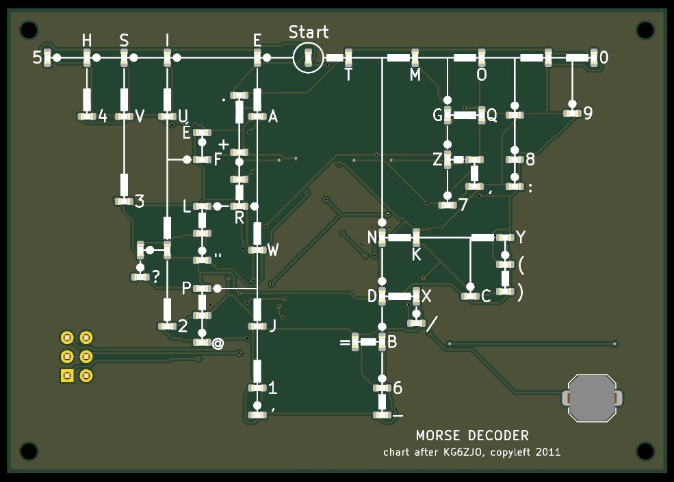
The complete pocket Morse decoder, 88 x 62 mm: every letter, the figures 0-9, the thirteen punctuation signs of the international code and the accented E, each with its own LED on Dave Nathanson's decoding chart. Press the key short for a dot and long for a dash, and the LED of the character you have reached lights; pause, and it blinks.
It runs on one CR2032 coin cell and sleeps between uses. The board was drawn with Youblob's Draw PCB, and its checks pass, but it has not been built yet.
Lanjutan
About 1 day, plus board delivery
Arahan
1
1
LED current and keying speed
LED current and keying speed
Memuatkan buku nota Jupyter…
2
2
The letters-only board, before it
The letters-only board, before it
The same design with 27 LEDs. This one adds the figures and the signs, 59 LEDs in all.
3
3
Read the chart
Read the chart
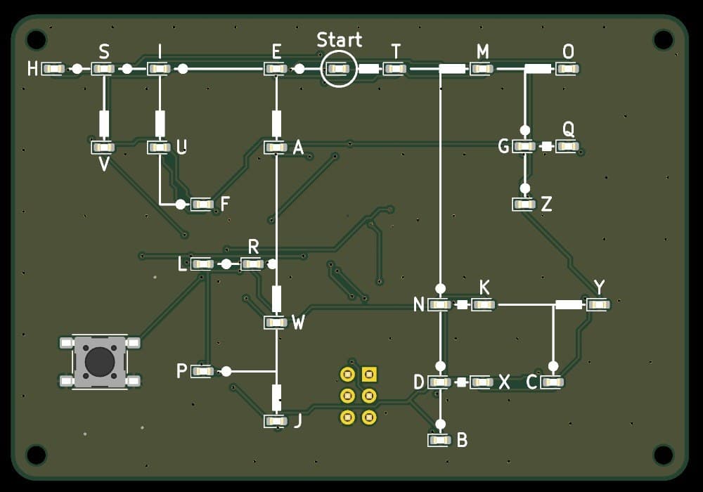
Dave Nathanson's (KG6ZJO) complete chart adds the figures to his letters: "A-Z and Numbers (I left off the punctuation & symbols for simplicity)". This board adds them back from ITU-R M.1677-1 on new branches: . , : ? ' - / ( ) " = + @ and the accented E. Eight unlabelled LEDs are waypoints on the way to a figure or sign.
4
4
The schematic
The schematic
ATmega328P on its internal 8 MHz clock, straight from the coin cell; 59 LEDs charlieplexed on nine lines (PC0-PC5, PD0, PD1, PD3) through 300 Ω resistors; the key on INT0; a 2x3 ISP footprint.
Memuatkan pemapar KiCanvas...
Pemapar Reka Bentuk PCB Profesional
5
5
The board
The board
Two layers, 88 x 62 mm. The chart, LEDs and key on the front; the chip, resistors, capacitors and cell holder on the back.
Memuatkan pemapar KiCanvas...
Pemapar Reka Bentuk PCB Profesional
6
6
Order the board
Order the board
Open the board in KiCad and plot Gerber and drill files (File > Fabrication Outputs). Order a two-layer board, 1.6 mm thick, from any board maker that takes Gerbers.
Bahan untuk langkah ini:
 Papan litar bercetak1 keping
Alatan diperlukan:
 Komputer dengan Arduino IDE
7
7
Solder the parts
Solder the parts
Back first: paste and reflow U1, R1-R10, C1-C3 and the cell holder BT1 with hot air. Then the front: the 59 red LEDs D1-D59 with pad 1 (cathode) as the board's assembly drawing shows, and the key SW1, a two-pad 6 x 6 mm switch to match its footprint. J1 is optional. Clean off the flux, then test each LED's direction with the meter's diode test.
Bahan untuk langkah ini:
 Pengawal mikro ATmega328P1 keping
 LED cip59 keping
 Perintang cip10 keping
 Kapasitor seramik cip3 keping
 Butang tekan1 keping
 Pemegang bateri1 keping
 Pes pateri (bebas plumbum)1 keping
 Dawai Pateri1 keping
Alatan diperlukan:
 Stesen kerja semula udara panas
 Alat pematerian
 Penyepit berhujung tirus
 Fluks
 Kanta Pembesar
 Multimeter
 Alkohol Isopropil 99 %
8
8
The firmware
The firmware
pocket_morse_decoder_complete.ino: every timing is a named constant at the top of the sketch. Board in the Arduino IDE: Arduino Pro or Pro Mini, ATmega328P (3.3V, 8 MHz).
pocket_morse_decoder_complete.inoarduino
9
9
Set the fuses and upload
Set the fuses and upload
Do not use Burn Bootloader: the Pro board setting expects a crystal, and this board has none. Hold an ISP programmer's 2x3 pins on J1 and set the internal 8 MHz clock: avrdude -c usbasp -p m328p -U lfuse:w:0xE2:m -U hfuse:w:0xD9:m -U efuse:w:0xFF:m. Then, in the Arduino IDE, use Sketch > Upload Using Programmer.
Alatan diperlukan:
 Pengatur cara AVR ISPKomputer dengan Arduino IDE
10
10
Print the back shell
Print the back shell
An open-front tray, 92.6 x 66.6 x 8.3 mm, with four standoffs for M2 screws, a notch and floor opening to slide the cell out and an opening under J1. PLA, 0.2 mm layers, 20 % infill, printed on its floor.
11
11
Fit the shell
Fit the shell
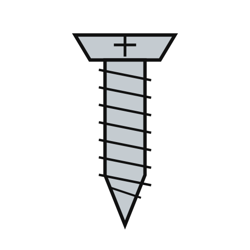
The standoffs hold the board 6.7 mm above the floor: measure your cell holder with a cell in it before you print. Check the holder's open end faces the board's bottom edge, where the shell's cell notch is. Slide in a CR2032 and screw the board into the shell with four M2 x 8 self-tapping screws.
Bahan untuk langkah ini:
 Filamen PLA1 keping
 Skru tap sendiri4 keping
 Bateri syiling CR20321 keping
Alatan diperlukan:
 Pencetak 3D filamen (FDM)
 Angkup Vernier
 Set pemutar skru jitu
12
12
Troubleshooting
Troubleshooting
Pocket Morse decoder troubleshooting.
Flow
Loading...
13
13
History and honest limits
History and honest limits
The letters and figures follow **Dave Nathanson**'s (KG6ZJO) complete chart of 2011, shared as copyleft. Where the signs sit is ours; their codes are ITU-R M.1677-1's. The board, sizes, parts and timings are ours, drawn with Youblob's Draw PCB: its ERC and DRC pass with no errors and every LED's wiring, code and label was checked against the firmware by script, but it has not been built, flashed or tested.
Bahan
12- 1 kepingPemegang Tempat
- 1 kepingPemegang Tempat
- 59 kepingPemegang Tempat
- 10 kepingPemegang Tempat
- 3 kepingPemegang Tempat
- Pemegang Tempat
- Pemegang Tempat
- 1 kepingPemegang Tempat
- 1 kepingPemegang Tempat
- 1 kepingPemegang Tempat
- 4 kepingPemegang Tempat
- 1 kepingPemegang Tempat
Alatan Diperlukan
12- Pemegang Tempat
- Pemegang Tempat
- 2 vendors sell this, none ship to you yetPemegang Tempat
- Pemegang Tempat
- Pemegang Tempat
- Pemegang Tempat
- Pemegang Tempat
- Pemegang Tempat
- Pemegang Tempat
- Pemegang Tempat
- Pemegang Tempat
- Pemegang Tempat
Fail reka bentuk
1Blueprint ini membuat

Blueprint berkaitan
Blueprint ini berkongsi pengetahuan — teknik, bahan atau prinsip

CC0 Domain Awam
Blueprint ini dikeluarkan di bawah CC0. Anda bebas menyalin, mengubah, mengedar, dan menggunakan karya ini untuk sebarang tujuan, tanpa meminta kebenaran.
Sokong Pembuat dengan membeli produk melalui Blueprint mereka di mana mereka memperoleh Komisen Pembuat ditetapkan oleh Penjual, atau cipta iterasi baru Blueprint ini dan sertakan ia sebagai sambungan dalam Blueprint anda sendiri untuk berkongsi hasil.