
Logic Gates from Relays
Arahan
Start from the telegraph relay
Start from the telegraph relay
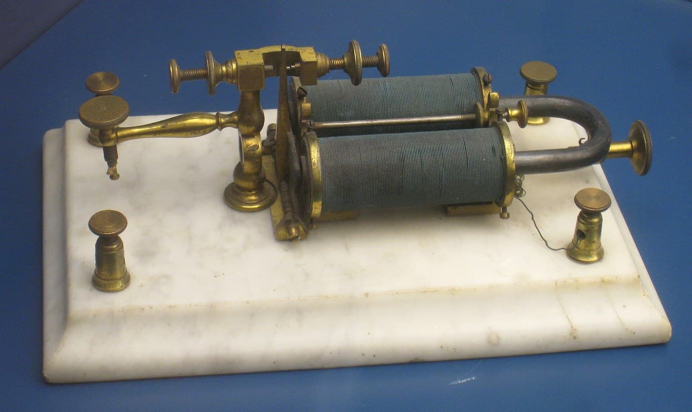
Build or re-read the relay first. It was invented to solve a completely different problem — a telegraph signal too weak to travel further, restored by using it to operate a local switch on a fresh battery.
Note the property that matters here and mattered not at all to its inventors: the thing that operates the switch is the same KIND of thing the switch controls. A lever needs a hand; a relay needs only another relay. That closure under composition is what makes logic possible, and it was sitting unused in telegraph offices for eighty years.
Wire AND, OR and NOT from contacts
Wire AND, OR and NOT from contacts
Three circuits, and every digital device ever built is made of them.
- AND: wire two relay contacts in SERIES between supply and lamp. The lamp lights only if both coils are energised.
- OR: wire two contacts in PARALLEL. The lamp lights if either coil is energised.
- NOT: use a normally-CLOSED contact. The lamp lights when the coil is NOT energised.
- Build all three and fill in a truth table for each by trying every input combination.
Series is AND, parallel is OR, normally-closed is NOT. That is Shannon's entire correspondence, and it is worth pausing on how unreasonable it is that a topology of wires should match an algebra of propositions.
Now the payoff: because it IS algebra, you can simplify circuits symbolically. De Morgan's laws say NOT(A AND B) equals NOT A OR NOT B — which means the same function can be built two different ways, and you pick whichever needs fewer contacts. Engineers had been optimising relay circuits by intuition; after 1937 they optimised them by algebra.Bahan untuk langkah ini:
 Geganti4 keping
 Set LED penunjuk1 set
 Kit Perintang1 kit
 Papan Berlubang / Papan Prototaip1 keping
 Wayar penyambung1 reel
Alatan diperlukan:
 Stesen Pematerian
 Multimeter Digital Gred Makmal
 Bekalan Kuasa Meja Boleh Laras
 Cermin Mata Keselamatan Jernih
Build the same logic as blocks
Build the same logic as blocks
Ruang Kerja Blockly
Loading Blockly workspace...
Alatan diperlukan:
 Komputer Meja
Simulate, simplify, and count the contacts
Simulate, simplify, and count the contacts
Alatan diperlukan:
Komputer MejaMeasure the switching time, and find the ceiling
Measure the switching time, and find the ceiling
Relay logic works perfectly and is slow. Measure exactly how slow, because that number ends the era.
- Drive a relay coil with a square wave and put the oscilloscope on both the drive and the contact output.
- Measure the delay from coil energising to contacts closing, and again for release.
- Watch the contact closure closely at high sweep speed.
- Chain three relays so each drives the next, and measure the total delay.
A relay takes something like 5 to 20 milliseconds to switch, and the contacts BOUNCE for a millisecond or two after closing. Chain them and the delays add, so a computation passing through fifty gates takes most of a second.
The bounce is its own problem: a single logical transition arrives as a burst of several, and any counter downstream counts them all. Debouncing exists because a mechanical contact does not close once.
So the ceiling is mechanical, not logical. The algebra is fine and the relay is honest; it simply has mass, and mass takes time to move. The escape is a switch with no moving parts at all — the vacuum tube, which switches in microseconds, and then the transistor, which does it without the heat. That is the rest of this batch.Bahan untuk langkah ini:
Geganti3 kepingKit Perintang1 kitAlatan diperlukan:
 Osiloskop
 Penjana FungsiMultimeter Digital Gred MakmalBekalan Kuasa Meja Boleh Laras
Bahan
5- 7 kepingPemegang Tempat
- 1 setPemegang Tempat
- Pemegang Tempat
- Pemegang Tempat
- 1 reelPemegang Tempat
Alatan Diperlukan
7- Pemegang Tempat
- Pemegang Tempat
- Pemegang Tempat
- Pemegang Tempat
- Pemegang Tempat
- Pemegang Tempat
- Pemegang Tempat
Blueprint berkaitan
Blueprint ini berkongsi pengetahuan — teknik, bahan atau prinsip
CC0 Domain Awam
Blueprint ini dikeluarkan di bawah CC0. Anda bebas menyalin, mengubah, mengedar, dan menggunakan karya ini untuk sebarang tujuan, tanpa meminta kebenaran.
Sokong Pembuat dengan membeli produk melalui Blueprint mereka di mana mereka memperoleh Komisen Pembuat ditetapkan oleh Penjual, atau cipta iterasi baru Blueprint ini dan sertakan ia sebagai sambungan dalam Blueprint anda sendiri untuk berkongsi hasil.