Push Buttons — SIK Circuit 5
Arahan
Parts & Introduction
Parts & Introduction
Push buttons are the simplest digital input. This experiment uses two buttons with an XOR logic gate: the LED turns on if you press either button, but turns off if you press both. You'll learn about digitalRead(), pull-up resistors, and boolean logic.
Parts Needed
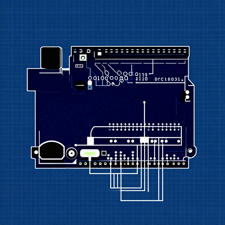
- 1x Arduino Uno + USB cable
- 1x Breadboard
- 2x Push Buttons
- 1x LED (any color)
- 1x 330Ω Resistor
- 2x 10KΩ Resistors (pull-ups)
- 7x Jumper Wires
Bahan untuk langkah ini:
 SparkFun Inventors Kit - V3.21 kit
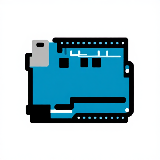 Arduino Uno R31 keping
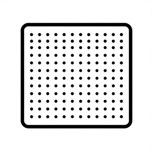 Breadboard1 keping
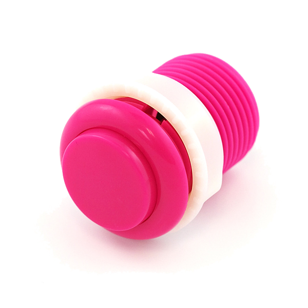 Push Button2 keping
 5mm LED1 keping
 330 Ohm Resistor1 keping10K Ohm Resistor2 keping
 Jumper Wires7 keping
Alatan diperlukan:
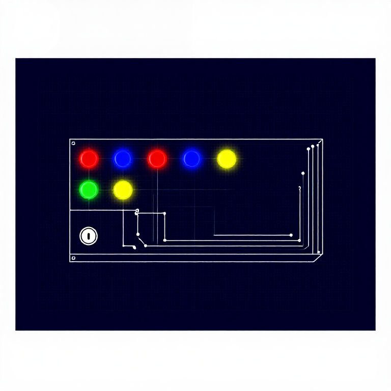
Hardware Hookup
Hardware Hookup
Wiring Instructions
- Place both push buttons across the center canyon of the breadboard.
- Button 1: Connect one pin to GND. Connect the opposite diagonal pin to Arduino Digital Pin 2. Add a 10K resistor between Pin 2 and 5V (pull-up).
- Button 2: Connect one pin to GND. Connect the opposite diagonal pin to Arduino Digital Pin 3. Add a 10K resistor between Pin 3 and 5V (pull-up).
- Connect LED positive leg to Digital Pin 13, negative leg through 330Ω resistor to GND.
Note: The pull-up resistors hold the input HIGH when the button is not pressed. Pressing the button connects the pin to GND (LOW).
Bahan untuk langkah ini:
Push Button2 keping5mm LED1 keping330 Ohm Resistor1 keping10K Ohm Resistor2 kepingBreadboard1 kepingJumper Wires7 kepingArduino Code
Arduino Code
Open the Arduino IDE and upload the following sketch to your Arduino board.
Bahan untuk langkah ini:
Arduino Uno R31 kepingAlatan diperlukan:
Test & Experiment
Test & Experiment
What You Should See
The LED turns on when you press either button individually. It turns off when you press both buttons simultaneously (XOR logic).
Troubleshooting
- Not responding: Push buttons are square — it's easy to put them in the wrong orientation. Try rotating 90°.
- LED always on or always off: Check the pull-up resistor connections. Without them, the input pin floats and reads random values.
Experiments to Try
- Change the logic to AND (both buttons required) or simple OR.
- Use the buttons to control an RGB LED — one button for color, one for brightness.
- Try using
INPUT_PULLUPmode to eliminate the external resistors.
Bahan
8- $105.00
- 1 kepingPemegang Tempat
- 1 kepingPemegang Tempat
- 2 keping$2.00
- Pemegang Tempat
- $3.00
- $3.00
- $5.00
You can swap these in
Can't get one of the materials? Swap it for an equivalent — these work just as well.
- Instead of Arduino Uno R3, try:
 Prototyping Shield for Arduino Uno (3-Pack)
 Arduino Uno R3 BoardArduino Uno
 - Instead of 5mm LED Assortment Kit (300pcs, 5 Colors), try:
 WS2812B NeoPixel LED Strip (1m, 60 LEDs)
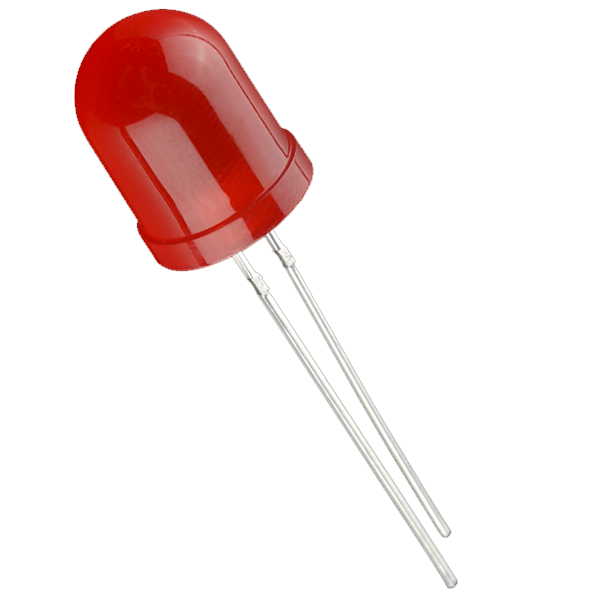 Diffused LED - 10mm
 RGB LED Strip 5050 (5m, Non-Addressable)
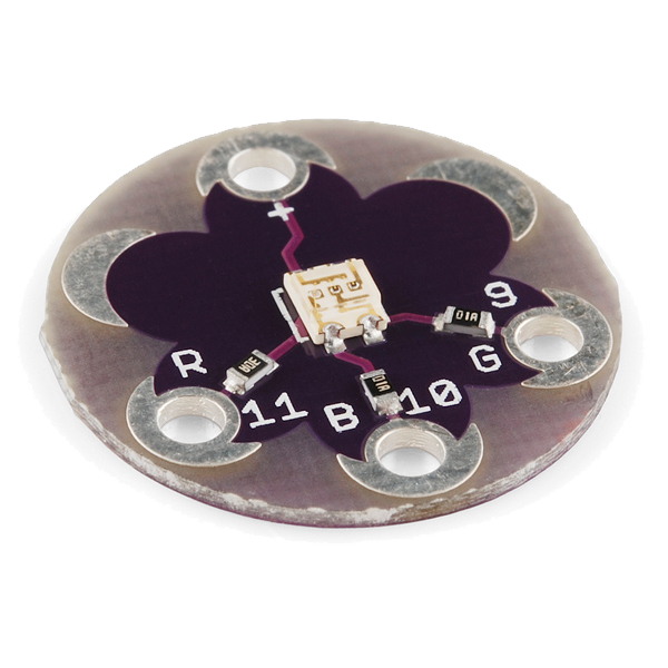 LilyPad Tri-Color LED
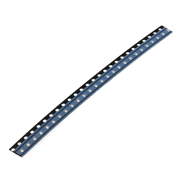 SMD LED 0603 - Strip of 25
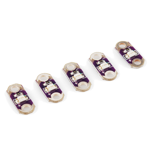 LilyPad LED - 5 pcs
 - Instead of Push Button - 33mm, try:
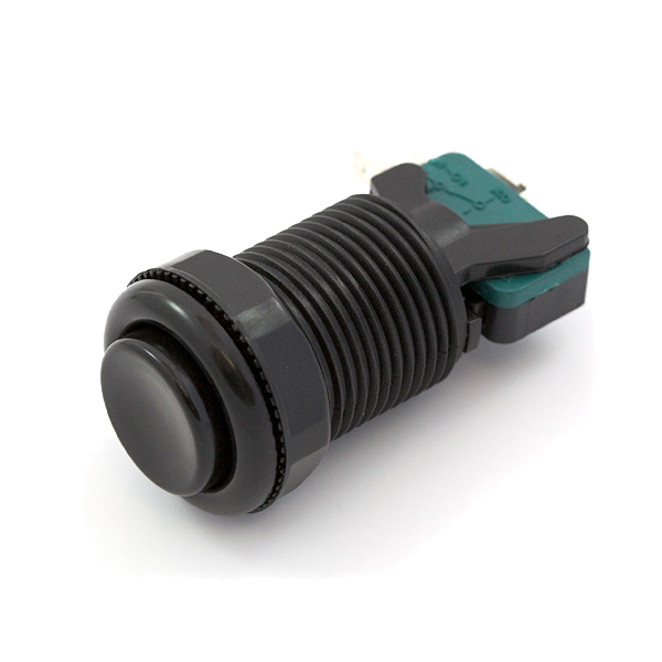 Concave Retro Gaming Button
 Toggle & Duffle Coat Button Set
 - Instead of Resistor 330 Ohm 1/6 Watt PTH - 20 pack, try:
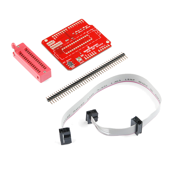 AVR ISP Shield - PTH Kit
Recommended for this build
Products makers often use with builds like this one.
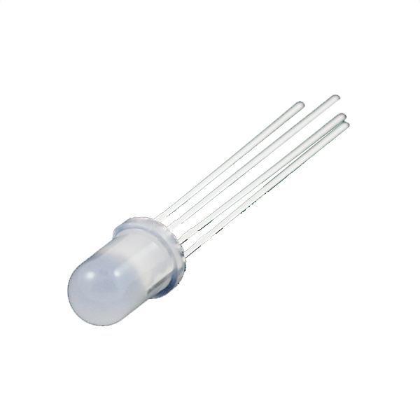 LED - RGB Diffused Common Cathode - 5mmFrequently used with this build's materials
 Diode KitFrequently used with this build's materials
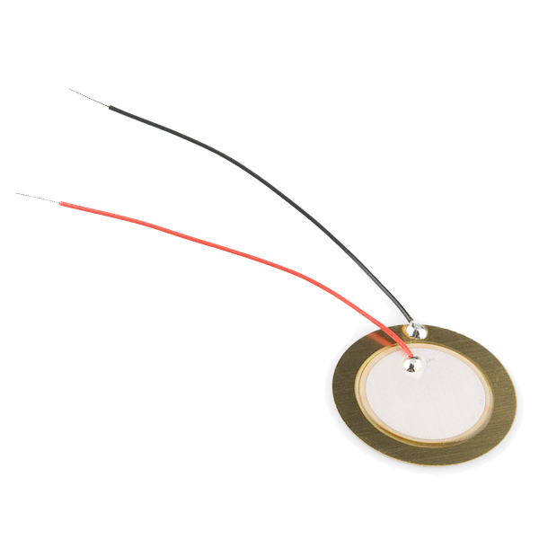 Piezo ElementUsed together and in similar builds
 Jumper Wire Kit (350pcs, M-M / M-F / F-F)Frequently used with this build's materials
 Servo MotorFrequently used with this build's materials
 USB CableFrequently used with this build's materials
 PotentiometerUsed together and in similar builds
Related blueprints
Other builds that share materials, tools, or techniques with this one.


CC0 Domain Awam
Blueprint ini dikeluarkan di bawah CC0. Anda bebas menyalin, mengubah, mengedar, dan menggunakan karya ini untuk sebarang tujuan, tanpa meminta kebenaran.
Sokong Pembuat dengan membeli produk melalui Blueprint mereka di mana mereka memperoleh Komisen Pembuat ditetapkan oleh Penjual, atau cipta iterasi baru Blueprint ini dan sertakan ia sebagai sambungan dalam Blueprint anda sendiri untuk berkongsi hasil.