IṢẸ́ ỌNÀ
ẸWÀ ÀTI ÌLERA
IṢẸ́ ỌWỌ́
ÀṢÀ ÀTI ÌTÀN
ÌṢERÉ
ÀYÍKÁ
OÚNJẸ ÀTI OHUN MÍMU
REVERSE ENGINEERING
SÁYẸ́ǸSÌ
ERÉ ÌDÁRAYÁ
ÌMỌ̀-Ẹ̀RỌ
ÀWỌN OHUN WÍWỌ̀
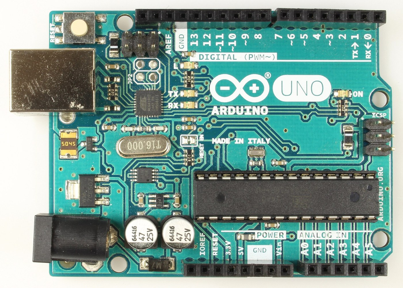


Arduino Uno R3: Assembled from Arduino's Open UNO-TH Rev3e Design Files and Flashed over ICSP
The Arduino Uno R3 is open hardware: Arduino publishes its schematic and board layout. This blueprint builds one from those files, part by part, then loads the firmware into its two processors.
Result: an Arduino Uno R3. An ATmega328P (16 MHz, 32 kB flash, 2 kB SRAM, 1 kB EEPROM) runs your programs; an ATmega16U2 turns USB into its serial link. It runs from USB (5.5 V at most) or 6-20 V at the DC jack.
Source: Arduino UNO-TH_Rev3e design files and the A000066 schematic and datasheet (Arduino, CC BY-SA). Unknown: how every bought part is made; no public source in hand says. The soldering method is ours. Picture: Wikimedia Commons.
Ilọsíwájú
1 day
Ìlànà
1
1
Get the bare board
Get the bare board
Have the two-layer board made to Arduino's UNO-TH_Rev3e board layout (the .brd file of the design files). Check it against the schematic before fitting anything.
Àwọn ohun èlò fún ìgbésẹ̀ yìí:
 Àwo PCB1 UNO-TH Rev3e layout
Àwọn irinṣẹ́ tí a nílò:
 Lúpù Ìgbéga
2
2
Fit the small surface-mount parts
Fit the small surface-mount parts
Solder the chip parts to their marked places: resistor arrays RN1 (10K), RN2 and RN4 (1K), RN3 (22R); R1, R2 (1M); capacitors C1, C2, C4-C7, C10 (100n), C3, C8 (1u), C9, C11 (22p); varistors Z1, Z2; ferrite bead L1; inductor L2 (10 uH); diodes D2, D3; LEDs ON (green), L, RX, TX (yellow). Ours: flux, tweezers and hot air or a fine iron, checked under a loupe.
Àwọn ohun èlò fún ìgbésẹ̀ yìí:
 Àkójọ rẹ́sístọ̀ chip4 RN1-RN4
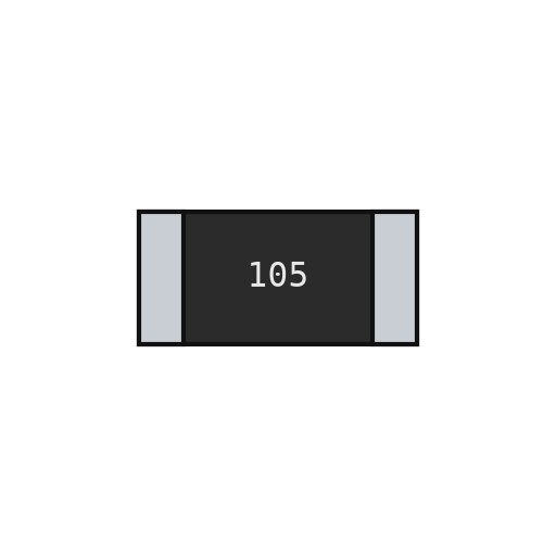 Rẹ́sístọ̀ chip2 1M
 Kápásítọ̀ seramiki chip11 7x100n, 2x1u, 2x22p
 Varistor chip2 Z1, Z2
 Ìlẹ̀kẹ̀ ferrite1 L1
 Inductor orí-ojú1 L2
 Diode orí-ojú2 D2, D3
 LED chip4 1 green, 3 yellow
 Wáyà Sọ́ldà1 a little
Àwọn irinṣẹ́ tí a nílò:
 Fúlọ́ksì
 Ìdìmú tí orí rẹ̀ mú
 Ibùdó àtúnṣe afẹ́fẹ́ gbígbóná
 Irin ìsúdìLúpù Ìgbéga
3
3
Fit the power and chip parts
Fit the power and chip parts
Solder the ATmega16U2 (U3), the 16 MHz resonator Y2 and crystal Y1, the 5 V regulator NCP1117 (U1) and 3.3 V regulator LP2985 (U2), the LMV358 op-amp (U5), the FDN340P transistor (T1), the M7 diode (D1), the 500 mA resettable fuse (F1) and the 47 uF capacitors PC1, PC2 with their polarity as marked.
Àwọn ohun èlò fún ìgbésẹ̀ yìí:
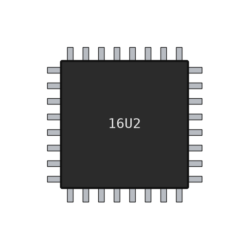 Microcontroller ATmega16U21 U3
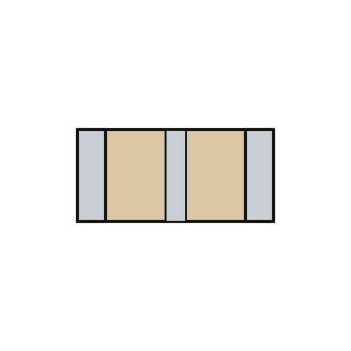 Resonator seramiki piezo1 Y2
 Kírísítà quartz1 Y1
 Olùtọ́sọ́nà fóltéèjì onílà2 U1 5 V, U2 3.3 V
 IC amplifier oníṣẹ́1 U5 LMV358
 MOSFET ọ̀nà-P1 T1Diode orí-ojú1 D1 M7
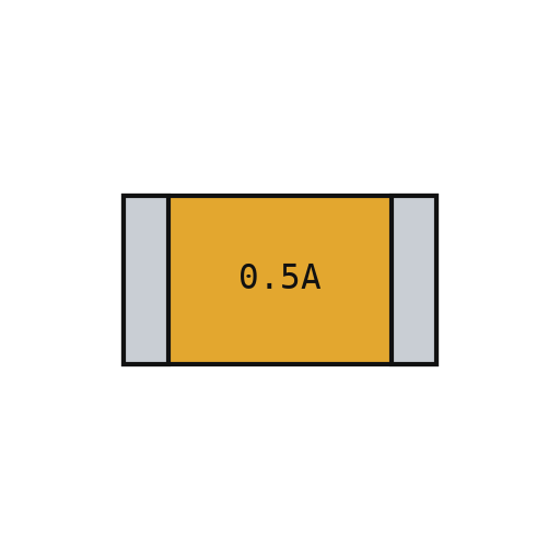 Fíúsì tí ó ń tún ara rẹ̀ ṣe1 F1
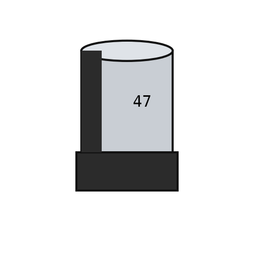 Kápásítọ̀ chip ọlọ́pá2 PC1, PC2Wáyà Sọ́ldà1 a little
Àwọn irinṣẹ́ tí a nílò:
Fúlọ́ksìÌdìmú tí orí rẹ̀ múIbùdó àtúnṣe afẹ́fẹ́ gbígbónáIrin ìsúdìLúpù Ìgbéga4
4
Fit the through-hole parts
Fit the through-hole parts
Solder the USB-B socket (X2), the DC jack (X1), the reset switch, the female headers (one 10-way, two 8-way, one 6-way) and the two 2x3 ICSP headers. Seat the ATmega328P in its place (ZU4).
Àwọn ohun èlò fún ìgbésẹ̀ yìí:
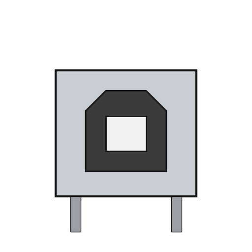 Ihò USB-B1 X2
 Ihò iná olórí yíyí1 X1
 Bọ́tìnì ìtẹ̀1 RESET
 Ìlà ọ̀pá ìsopọ̀6 10x1, 2x 8x1, 6x1 female; 2x 3x2 ICSP
 Microcontroller ATmega328P1 ZU4Wáyà Sọ́ldà1 as needed
Àwọn irinṣẹ́ tí a nílò:
Irin ìsúdì5
5
Flash and check
Flash and check
Check with a meter that 5 V and GND are not shorted. Through the ICSP headers, load the USB-to-serial firmware into the ATmega16U2 and the bootloader into the ATmega328P. Plug in USB: the green ON LED lights, and the blink test in the next step flashes the L LED. Ours: an AVR ISP programmer and a multimeter.
Àwọn ohun èlò fún ìgbésẹ̀ yìí:
 Firmware Arduino Uno1 download
Àwọn irinṣẹ́ tí a nílò:
 Òǹwọ̀n iná mànàmáná onírúurú
 Olùkọ ètò AVR ISP
 Okùn USB-B
6
6
The blink test
The blink test
blink_test.ino: the same check as Arduino's Blink example. Upload it over USB from the Arduino IDE with the board set to Arduino Uno; the L LED on pin 13 turns on for one second and off for one second, over and over. If it does, both processors, the USB link and the bootloader work.
blink_test.inocpp
Àwọn irinṣẹ́ tí a nílò:
Okùn USB-BÀwọn ohun-èlò
24- 1 UNO-TH Rev3e layoutÀyè
- 4 RN1-RN4Àyè
- 2 1MÀyè
- 11 7x100n, 2x1u, 2x22pÀyè
- 2 Z1, Z2Àyè
- 1 L1Àyè
- 1 L2Àyè
- 1 D1 M7Àyè
- 4 1 green, 3 yellowÀyè
- 1 as neededÀyè
- Àyè
- Àyè
- 1 Y1Àyè
- 2 U1 5 V, U2 3.3 VÀyè
- 1 U5 LMV358Àyè
- 1 T1Àyè
- Àyè
- 2 PC1, PC2Àyè
- 1 X2Àyè
- Àyè
- Àyè
- Àyè
- Àyè
- 1 downloadÀyè
Ìtọ́nisọ́nà yìí ń ṣe
Blueprint tó jọra
Àwọn blueprint wọ̀nyí pín ìmọ̀ — ọ̀nà, ohun-èlò tàbí ìlànà
CC0 Àgbègbè Gbogbogbò
Blueprint yìí ti jáde lábẹ́ CC0. O lè ṣe àdàkọ, yí padà, pín, àti lò láìsí ìyọ̀ǹda.
Ṣàtìlẹ́yìn Olùṣẹ́dá nípa rírà àwọn ọjà nipasẹ̀ Blueprint wọn Ẹ̀san Olùṣẹ́dá tí àwọn Olùtajà gbé kalẹ̀, tàbí ṣẹ̀dá àtúnṣe tuntun ti Blueprint yìí kí o sì fi sínú Blueprint rẹ gẹ́gẹ́ bí ìsopọ̀ láti pín owó-wíwọlé.