

Brush Dynamo
A battery is a chemical bank account. It holds a fixed amount of energy, it runs down, and refilling it means replacing the chemicals. Every electrical demonstration before about 1870 ran on batteries, which is why electricity stayed a laboratory curiosity: nobody could afford to light a street with zinc.
A dynamo does not store energy — it converts it. Turn the shaft and it makes current for as long as something keeps turning. Water, steam or a horse becomes electricity continuously. That is the difference between an experiment and an industry.
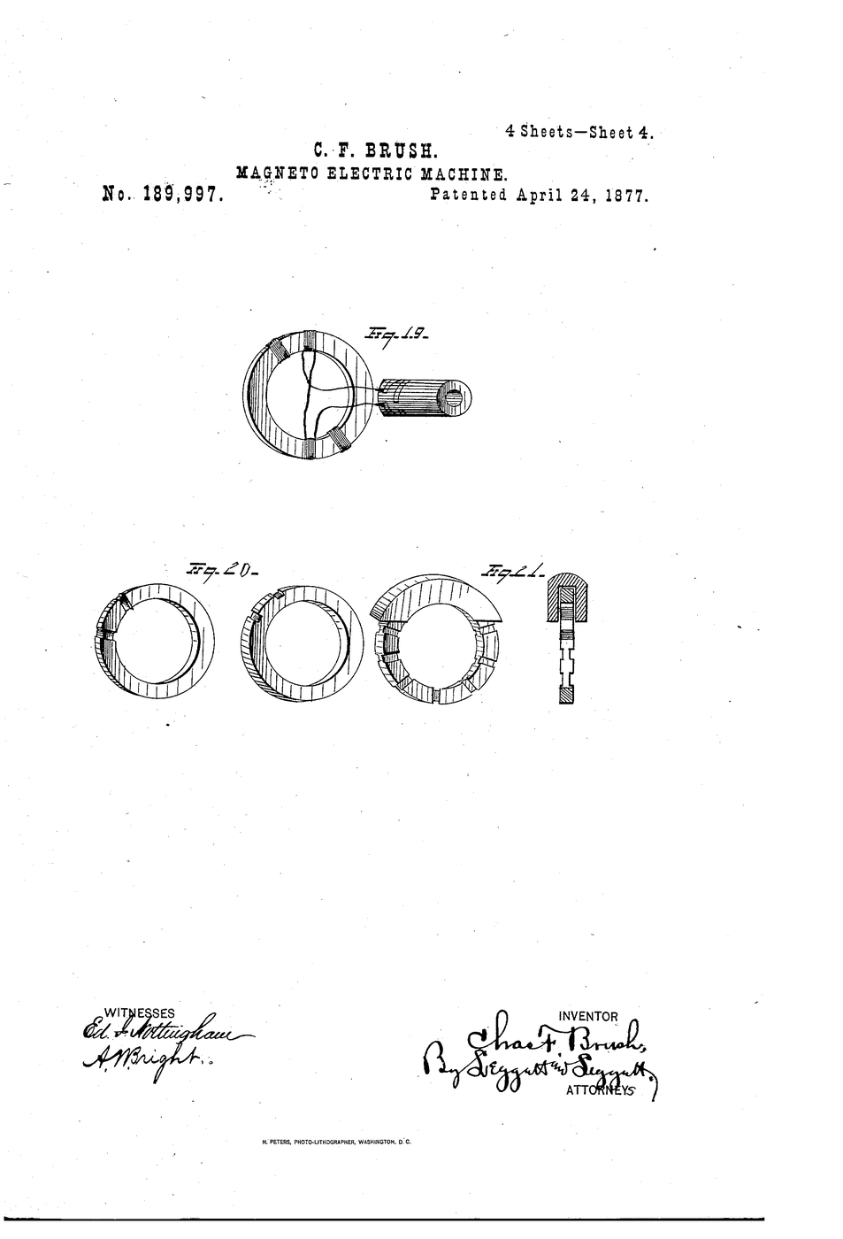
Brush's patent does not claim the dynamo. Magneto-electric machines already existed. His specification says plainly that his invention "consists of improvements in the armature and in the arrangement of commutators" — the two parts that decide whether the machine delivers usable, steady current or a rough pulsing mess.
US Patent 189,997, "Improvement in magneto-electric machines", application filed 11 November 1876 and granted 24 April 1877 to Charles F. Brush of Cleveland, Cuyahoga County, Ohio.
Ìlànà
Read what US 189,997 actually claims
Read what US 189,997 actually claims
Brush writes that his invention "consists of improvements in the armature and in the arrangement of commutators". Not the dynamo — two components inside it. Write those two words down; the whole build is about them.
Cut a plywood base and mount the field magnet
Cut a plywood base and mount the field magnet
Cut a plywood base about 150 x 100 mm. Clamp a horseshoe magnet to it so the two poles face each other with a 25 mm gap. This gap is the field.
Àwọn ohun èlò fún ìgbésẹ̀ yìí:
 Pìláwọ́ọ̀dù Bíṣì Baltiki1 ewé
Àwọn irinṣẹ́ tí a nílò:
 Magnet onírísí bàtà ẹṣin
Wind a 200-turn armature coil
Wind a 200-turn armature coil
Wind 200 turns of 22 AWG enamelled copper wire onto a 40 mm former. Keep the turns tight and count them — turns decide voltage.
Àwọn ohun èlò fún ìgbésẹ̀ yìí:
 Okùn bàbà oní enamel 22 AWG1 ìyípo
Mount the coil on a dowel shaft
Mount the coil on a dowel shaft
Fix the coil to a dowel so it spins freely between the magnet poles. Leave both wire ends long and free.
Àwọn ohun èlò fún ìgbésẹ̀ yìí:
 Òpó Igi Dòwẹ̀lì1 ẹyọ
Scrape the enamel off both wire ends
Scrape the enamel off both wire ends
Scrape 15 mm of enamel from each end back to bright copper. Enamel is an insulator — unscraped ends make no contact and the machine reads zero.
Àwọn irinṣẹ́ tí a nílò:
 Ọ̀bẹ Iṣẹ́ Ọwọ́
Measure the raw output as alternating current
Measure the raw output as alternating current
Touch the multimeter probes to the two bare ends, set to AC volts, and spin the shaft steadily. Record the reading. This is what the coil makes before any commutator.
Àwọn irinṣẹ́ tí a nílò:
 Òṣùwọ̀n Oníṣirò Díjítà Ìpele Yàrá Ìwádìí
Switch the meter to DC and spin again
Switch the meter to DC and spin again
Same coil, same speed, meter on DC volts. The reading hovers near zero and twitches either side. The current is reversing every half turn.
Build a two-segment commutator
Build a two-segment commutator
Wrap a short copper tube on the shaft and cut it into two segments separated by a gap. Solder one coil end to each segment.
Àwọn ohun èlò fún ìgbésẹ̀ yìí:
 Ọ̀pá bàbà 10 mm1 ẹyọ
Fit two brushes bearing on the segments
Fit two brushes bearing on the segments
Spring two stiff wires against opposite sides of the commutator. Position them so they cross the gap at the moment the coil output passes through zero.
Measure DC output through the commutator
Measure DC output through the commutator
Meter on DC, probes on the brushes, spin at the same speed as step 6. Now you get a steady positive reading. The commutator flips the connection every half turn, so the output never reverses.
Double the segments and compare the ripple
Double the segments and compare the ripple
Rebuild with four segments instead of two. Spin and watch the meter's fluctuation. More segments, smoother current — this is the arrangement Brush's patent is about.
Vary speed and plot voltage against turns per second
Vary speed and plot voltage against turns per second
Spin at three counted speeds and record voltage for each. Plot the pairs. The line is close to straight: voltage rises with speed, which is why a dynamo needs a governed prime mover.
Short the output and feel the load
Short the output and feel the load
Connect the brushes through a small lamp and spin again. The shaft becomes harder to turn. That extra effort is the electrical energy — the machine converts, it does not create.
Àwọn irinṣẹ́ tí a nílò:
 Bọ́ọ̀bù iná
History & Context — the man who lit the public square
History & Context — the man who lit the public square
The patent. US 189,997, "Improvement in magneto-electric machines", application filed 11 November 1876, granted 24 April 1877, to Charles F. Brush of Cleveland, Cuyahoga County, Ohio. The specification opens by placing the field precisely: the invention "relates to magneto-electric machines, or apparatus for the conversion of mechanical into electrical energy".
Read the scope carefully, because it is easy to overstate. Brush did not invent the dynamo, and this patent does not claim to. Machines converting rotation into current existed for decades before it — Faraday had shown the principle in 1831, and Gramme, Siemens and Wheatstone all had working generators. What Brush claims, in his own words, is "improvements in the armature and in the arrangement of commutators". The drawings bear this out: of the ten figures, most are devoted to armature grooving and to developed views of commutator cylinders with varying segment counts. It is a patent about two components, and calling it "the Brush dynamo patent" is a shorthand that hides what he actually contributed.
Why the commutator is the interesting part. A coil rotating in a magnetic field produces alternating current — steps 6 and 7 show that with nothing more than a meter. For arc lighting, which was the market, that was inconvenient: carbon arcs were run in long series strings and needed current that behaved predictably. A commutator is a mechanical rectifier, a rotary switch geared to the coil that reverses the external connection at exactly the instant the internal voltage reverses. Get the timing right and the output never crosses zero. Get the segment count up and the remaining ripple shrinks, which is precisely what step 11 measures.
What Brush did with it. His machines were built for series arc lighting, and his real commercial insight was regulation — keeping current steady as lamps were switched in and out of a long series circuit, which is a harder problem than making current at all. In 1879 Cleveland's Public Square was lit by Brush arc lamps, and Brush arc lighting spread through American and European cities through the 1880s. It is worth being clear that arc light and incandescent light were different markets solving different problems: arc lamps were brilliant, noisy, and suited to streets and large halls; Edison's filament lamp, patented the following year, was dim by comparison and suited to rooms. They coexisted for decades.
The honest limit of this build. Your machine is a single-coil demonstration, and a real dynamo of the period had a many-section armature feeding a many-segment commutator, which is why its output was far smoother than anything you will measure here. What transfers exactly is the principle: rotation makes alternating current, and a commutator is what turns it into current a nineteenth-century circuit could use.
Àwọn ohun-èlò
4- Àyè
- 1 ìyípoÀyè
- 1 ẹyọÀyè
- 1 ẹyọÀyè
Àwọn irinṣẹ́ tó nílò
4- Àyè
Blueprint tó jọra
Àwọn blueprint wọ̀nyí pín ìmọ̀ — ọ̀nà, ohun-èlò tàbí ìlànà

CC0 Àgbègbè Gbogbogbò
Blueprint yìí ti jáde lábẹ́ CC0. O lè ṣe àdàkọ, yí padà, pín, àti lò láìsí ìyọ̀ǹda.
Ṣàtìlẹ́yìn Olùṣẹ́dá nípa rírà àwọn ọjà nipasẹ̀ Blueprint wọn Ẹ̀san Olùṣẹ́dá tí àwọn Olùtajà gbé kalẹ̀, tàbí ṣẹ̀dá àtúnṣe tuntun ti Blueprint yìí kí o sì fi sínú Blueprint rẹ gẹ́gẹ́ bí ìsopọ̀ láti pín owó-wíwọlé.