Building Ctesibius' Force Pump — The First Double-Acting Piston Pump
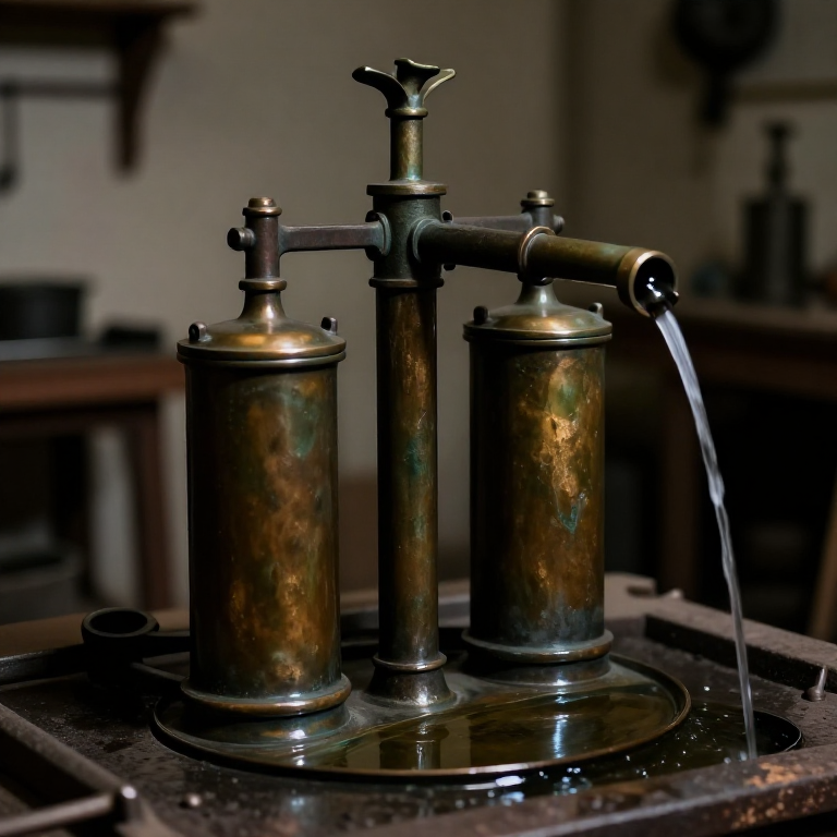
Ctesibius of Alexandria (~285–222 BCE) was the first known engineer to systematically exploit compressed air and hydraulic pressure as engineering tools. Working in Alexandria's Mouseion (the precursor institution to the Library of Alexandria), he invented the double-acting force pump — a device with two cylinders, two pistons, and a system of check valves that produces a continuous pressurised water stream by alternating the push-and-pull strokes of the two pistons. It is the direct ancestor of every reciprocating pump, from hand-operated bilge pumps on ancient warships to modern diesel fuel injectors.
Hero of Alexandria, writing two centuries after Ctesibius, described the device in detail in 'Pneumatica'. The key innovation was the check valve — a flap or ball that allows water to flow in only one direction. Without check valves, each piston stroke would simply push water back the way it came. With two check valves per cylinder (one on the inlet, one on the outlet), each piston stroke delivers water to the outlet while simultaneously drawing in a fresh charge on the suction stroke. Two cylinders working in opposite phase (one pushing while the other pulls) smoothed the delivery to near-continuous flow.
The Romans used Ctesibius' force pump extensively for firefighting — the 'sipho' (from Greek siphon) carried on Roman fire brigades (vigiles) was a direct implementation of the double-acting pump, capable of projecting a jet of water onto burning buildings. The Pompei excavations yielded a remarkably intact bronze force pump dating to approximately 1st century CE, confirming the device's widespread practical use. The same mechanical principle drives the piston pumps in modern automotive power-steering systems, hydraulic jacks, and hand-operated well pumps in rural communities worldwide.
Instructions
Understand the double-acting cycle before fabrication
Understand the double-acting cycle before fabrication
The double-acting force pump has two cylinders working in parallel opposition. Label them Cylinder A and Cylinder B. When piston A pushes down (delivery stroke): the A inlet valve closes (preventing back-flow into the water source), the A outlet valve opens (forcing water into the common outlet pipe), while simultaneously piston B pulls up (suction stroke): the B inlet valve opens (drawing water from the source into cylinder B), the B outlet valve closes (preventing outlet water from flowing back into cylinder B). On the return stroke, A and B swap roles.
The result is that the outlet receives water on every half-stroke of the operating beam — near-continuous flow. The check valves are the critical components: if either inlet valve leaks (allows back-flow on the delivery stroke), the cylinder loses its prime and delivers air instead of water. If either outlet valve leaks, the delivery pressure drops and flow reverses during suction strokes. Build all four check valves with care equal to the cylinders themselves.
Cast or bore the cylinder barrels from bronze
Cast or bore the cylinder barrels from bronze
The cylinders must have a smooth, consistent bore so the piston seals effectively. Bronze (an alloy of copper and tin, typically 88–90% copper and 10–12% tin by mass) is the correct material — it resists corrosion, can be cast to near-shape, and can be finished by boring and scraping to a smooth internal surface. Cast each cylinder as a thick-walled tube approximately 5 cm internal diameter, 20 cm long, and 1.5 cm wall thickness. The Pompeii pump used cylinders approximately 4–5 cm in diameter — large enough to deliver a useful flow of 5–10 litres per minute at 60 strokes per minute.
After casting, bore the cylinder interior smooth using a hardwood boring bar fitted with a scraper blade, driven by a bow drill or a hand brace. Work the boring bar in long strokes, lubricating with olive oil, until the bore is smooth enough that a candleflame held inside shows no visible pits or ridges. Test the bore's roundness with a plug gauge (a turned bronze rod 0.5 mm smaller than the target bore diameter) — it should slide freely without rocking.
Tools needed:
 Hammer (2 kg)
Turn the pistons from bronze rod
Turn the pistons from bronze rod
Each piston must fit the cylinder bore with a clearance of 0.5–1 mm — tight enough that leather packing can seal the gap, loose enough that the piston does not bind from thermal expansion or slight bore irregularity. Turn or file the piston to a close fit with the cylinder, checking constantly with the actual cylinder as the gauge. The Pompeii pump's pistons were bronze discs approximately 3 cm tall and fitted with iron connecting rods to the operating beam above.
Machine a circumferential groove 5 mm wide × 5 mm deep around each piston's outer surface, approximately 1 cm from the top. This groove receives the leather packing that seals the piston-to-bore gap. Cut a strip of thick vegetable-tanned leather (2 mm thick) to exactly the piston circumference in length and 8 mm wide, soak it in olive oil for 30 minutes to make it supple, then press it into the groove. The oil-swollen leather fills the groove and bears against the cylinder bore, forming a pressure-tight running seal.
Tools needed:
 Sharp Knife
Fabricate the four check valves from bronze plate
Fabricate the four check valves from bronze plate
Each check valve consists of a bronze disc (the valve seat) with a central hole 1.5 cm diameter, and a slightly larger bronze disc (the flap) 2 cm diameter and 1 mm thick, positioned to cover the seat hole from one side. When pressure pushes from below the seat, the flap lifts and allows flow. When pressure reverses, the flap seals onto the seat hole and stops reverse flow. The seat and flap must be lapped (ground together with fine abrasive paste — powdered emery mixed with olive oil) until they form a flat-to-flat seal with no visible light gap when held up to a candle.
Alternatively, use ball check valves: a bronze or iron ball bearing slightly larger than the seat hole, held loosely in a cage above the seat. The ball drops onto the seat under gravity and back-pressure, sealing the hole; forward pressure lifts the ball off the seat. Ball valves are simpler to make than flap valves and less prone to sticking. The Pompeii pump used swing-plate valves similar to the flap design.
Tools needed:
 Grinding Stone
Build the valve housings and connect to cylinders
Build the valve housings and connect to cylinders
Each cylinder requires two valve housings: one at the bottom for the inlet check valve (drawing water from the source into the cylinder on the suction stroke) and one at the top for the outlet check valve (delivering water to the common outlet on the delivery stroke). The inlet valve housing connects to a submerged inlet pipe or suction tube immersed in the water source. The outlet valve housing connects to the common outlet pipe that leads to the discharge point.
Cast or solder the valve housings from bronze, with threaded or press-fit connections to the cylinder ends. The inlet connection should point downward or sideways; the outlet should point upward and connect to the common outlet manifold above both cylinders. Seat the check valves in their housings with the orientation correct — an inlet check valve installed backward (blocking flow into the cylinder instead of blocking back-flow) is the most common assembly error and produces a pump that delivers no water regardless of how correctly everything else is built.
Cast the common outlet manifold
Cast the common outlet manifold
The common outlet manifold is a bronze box that receives the pressurised delivery from both outlet check valves and combines them into a single outlet pipe. It also serves as an air chamber (the 'pulsation dampener'): an enclosed air pocket in the manifold compresses as delivery pressure rises on each piston stroke and expands during the suction half-stroke, smoothing the pressure fluctuation and producing a steadier flow. Without this air cushion, the flow surges and pulses with each stroke.
Cast the manifold with an internal volume approximately equal to the swept volume of one cylinder (the piston area multiplied by the stroke length). Include a removable plug at the top to allow re-charging the air cushion with air if it becomes water-logged over time. Connect the two cylinder outlet valves to the underside of the manifold and the discharge pipe to one side. The discharge pipe should be at least equal in diameter to the cylinder bore to avoid restricting the outlet flow.
Build the operating beam (rocking arm)
Build the operating beam (rocking arm)
The operating beam is a horizontal lever pivoted at its centre on a fulcrum post, with one piston rod connected to each end of the beam. As one end of the beam descends (pushing one piston down), the other end rises (pulling the other piston up). This seesaw motion drives the two cylinders in precise opposition — when piston A is at the bottom of its delivery stroke, piston B is at the top of its suction stroke, and vice versa. The beam must be rigid enough to transmit the full pumping force without flexing.
Make the beam from straight-grained oak approximately 5 cm × 8 cm in cross-section and long enough to provide the desired stroke length. For 10 cm piston stroke, the beam ends must travel 10 cm vertically — with a 60 cm half-length from pivot to end, a 10 cm vertical end movement requires an angular rotation of arcsin(10/60) ≈ 10°, which is comfortable for manual operation. Pivot the beam on a bronze pin through a hardwood or bronze fulcrum bracket mounted above and between the two cylinders.
Materials for this step:
 Hardwood Block2 pieces
Connect piston rods to the operating beam
Connect piston rods to the operating beam
Each piston is connected to the corresponding beam end by an iron piston rod approximately 1 cm diameter. The rod must transmit push force (on the delivery stroke) and pull force (on the suction stroke) — this means the rod must be in tension and compression alternately, so the connections at both ends must be positive (no relying on gravity alone to maintain contact). Pin the rod's upper end to the beam with an iron clevis pin through the beam end; pin the rod's lower end to the piston with a cross-pin through a drilled hole in the piston crown.
The piston rod must be aligned exactly vertically with the cylinder bore — any angular misalignment creates a side-load that pushes the piston against the cylinder wall, increasing friction and accelerating wear on the leather packing. Check alignment by lowering the piston into the cylinder on its rod with the beam in the mid-position: the rod should hang plumb without touching the cylinder wall. Adjust the beam pivot position or the cylinder mounting until plumb is achieved.
Fit the suction pipe and prime the pump
Fit the suction pipe and prime the pump
Connect the inlet valve housings to a common suction pipe (or individual suction tubes) that leads to the water source. The suction pipe must be air-tight — any air leak on the suction side means the piston draws in air instead of water, breaking the prime. The theoretical maximum suction lift of any piston pump is 10.3 metres (equal to atmospheric pressure supporting a column of water) but in practice 5–6 metres is the reliable limit with leather-sealed pistons and joints sealed with pine pitch rather than machined metal.
Prime the pump before first operation: fill the cylinders and valve housings completely with water by pouring through a removable plug at the top of each cylinder. The priming water creates the liquid seal that allows the check valves to work and the pistons to create suction pressure. Without priming, the pistons compress and expand air ineffectually — the pump simply breathes without drawing water. Operate the beam slowly by hand for the first 20 strokes to allow air bubbles to purge through the outlet before applying full working speed.
Test delivery pressure and flow rate
Test delivery pressure and flow rate
At 60 strokes per minute (30 full cycles of the rocking beam) with a 10 cm stroke and 5 cm bore (swept volume per stroke = π/4 × 5² × 10 = 196 cm³ ≈ 0.2 litres), the theoretical flow rate is 0.2 × 30 × 2 cylinders = 12 litres per minute. Actual flow will be 70–80% of theoretical due to valve leakage, piston bypass, and pipe friction — expect 8–10 litres per minute. This matches the Roman firefighting application: 10 litres per minute is a substantial jet when delivered at 0.5–1 bar gauge pressure through a nozzle 1.5 cm in diameter.
Test delivery pressure by measuring the height to which the pump can project water from a vertical open tube attached to the outlet manifold. A flow rate of 10 litres per minute and a delivery head of 5 metres (0.5 bar) represents a hydraulic power output of approximately 8 watts — modest by modern standards, but achieved with a compact hand-powered device weighing perhaps 15–20 kg and operable by one person. The Roman firefighting version (the sipho) used two operators at the beam for higher flow rates.
Maintenance of leather seals and check valves
Maintenance of leather seals and check valves
The leather piston seals are the most maintenance-intensive component. Leather packing shrinks and hardens when dry and left out of water, losing its sealing ability. If the pump will be out of service for more than a week, soak the leather seals in linseed oil or animal fat before storage to prevent drying. On recommissioning, re-soak the pump in water for 30 minutes before attempting to prime and operate it — the leather needs time to swell back to its sealing dimensions.
Check valve lapping (re-grinding the seat-to-flap mating surfaces) should be performed annually or whenever delivery output drops more than 25% from commissioning performance. Remove the valve housing plugs, extract the valve flaps, and regrind seat and flap together with fine emery paste until the mating surfaces show a consistent grey contact pattern all the way around the seat opening with no bright (uncontacted) spots. A perfectly lapped check valve can hold 1 bar back-pressure without leaking — test by applying air pressure with a bellows and verifying no bubbles at the joint with soapy water.
Historical context — the Roman fire brigade application
Historical context — the Roman fire brigade application
The Roman vigiles (fire brigade) were established by Augustus around 6 CE and stationed in seven cohorts across Rome's fourteen districts. Each cohort carried several sipho (Ctesibian force pumps) mounted on wheeled carts, filled by a bucket brigade from the nearest cistern or aqueduct tapping point. The historical record describes pumps capable of projecting water onto first-storey fires, suggesting working pressures sufficient to lift water 4–5 metres through a nozzle — consistent with the design parameters of this blueprint.
The Pompeii pump, now in the Naples National Archaeological Museum (inventory 75202), remains the best-preserved example: two bronze cylinders 4.2 cm internal diameter, 18 cm stroke, with a rocking beam operated by handles at each end. The surviving pump weighs approximately 12 kg and could have delivered roughly 7–8 litres per minute at one man's pumping speed. Rome's chronic fire risk in densely packed insulae (apartment blocks) made the force pump as critical to urban infrastructure as the aqueduct that supplied its water.
Materials
1- 2 piecesPlaceholder
Tools Required
3- Placeholder
- Placeholder
- Placeholder
Connected Blueprint Materials
Related Blueprints
These blueprints share knowledge with this one — techniques, materials, or principles that connect them in the learning graph.
Related blueprints
Other builds that share materials, tools, or techniques with this one.
CC0 Public Domain
This blueprint is released under CC0. You are free to copy, modify, distribute, and use this work for any purpose, without asking permission.
Support the Maker by purchasing products through their Blueprint where they earn a Maker Commission set by Vendors, or create a new iteration of this Blueprint and include it as a connection in your own Blueprint to share revenue.