IṢẸ́ ỌNÀ
ẸWÀ ÀTI ÌLERA
IṢẸ́ ỌWỌ́
ÀṢÀ ÀTI ÌTÀN
ÌṢERÉ
ÀYÍKÁ
OÚNJẸ ÀTI OHUN MÍMU
REVERSE ENGINEERING
SÁYẸ́ǸSÌ
ERÉ ÌDÁRAYÁ
ÌMỌ̀-Ẹ̀RỌ
ÀWỌN OHUN WÍWỌ̀
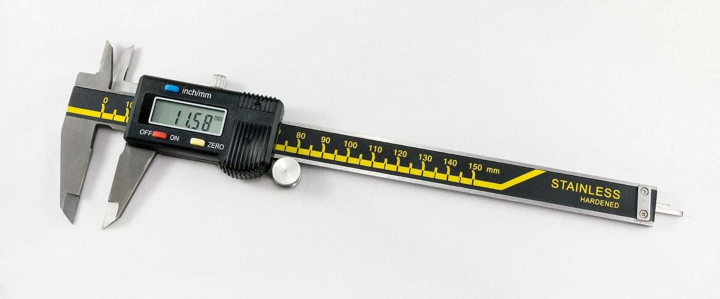


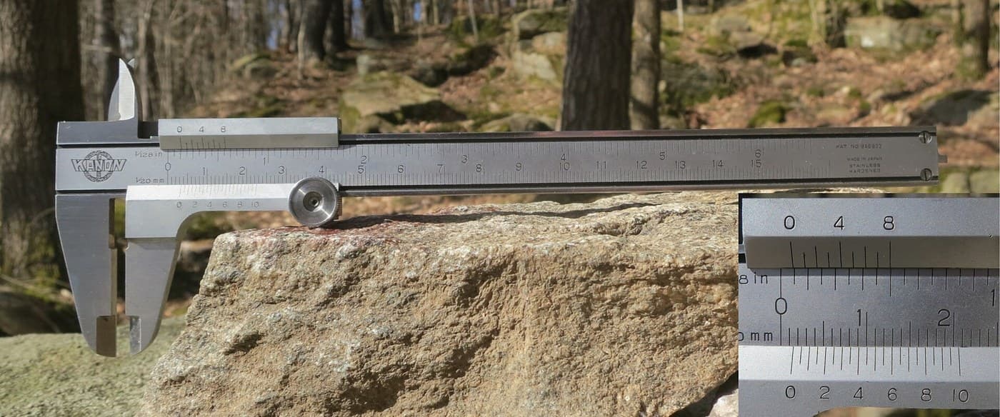
Digital Caliper: Capacitive Scale and Slider with Two-Chip Electronics (Baxter and Buehler, Starrett, 1986)
A six-inch caliper that reads out on a display. Under the slide, a strip of etched copper bars runs along the beam. Electrodes on the slider pass a signal through the bars by capacitance, and the slider's electronics count the bars crossed and work out the position in between.
Result: a digital caliper reading in inches or millimetres, repeatable to a ten-thousandth of an inch, with floating zero, peak hold and high/low limits. It runs on two 1.5 V cells at 10-50 microamps.
Source: L. K. Baxter and R. J. Buehler (L. S. Starrett Co.), US Patent 4,586,260 (1986). Unknown: the metal of the beam, slide and rod, their dimensions, the processor's program, and how the chips and display are made. Ours: the etchant, photoresist and glue. Picture: Wikimedia Commons.
Ilọsíwájú
2 days
Ìlànà
1
1
Etch the scale
Etch the scale
Etch the scale pattern onto a strip of copper-clad epoxy fibreglass with photoresist and etchant. Each copper bar is 0.40 inch long, with a wider centre 0.12 inch long and two ends 0.14 inch long. Space the bars on 0.05 inch centres: the centres sit 0.004 inch apart, the ends 0.025 inch apart. Run the pattern the full length of the scale. Ours: dry film resist and ferric chloride.
Àwọn ohun èlò fún ìgbésẹ̀ yìí:
 Àwo PCB tí kò ní nǹkan (tí a fi bàbà bò)1 strip, length of the beam
Àwọn irinṣẹ́ tí a nílò:
 Fíìmù gbígbẹ ìdènà ìmọ́lẹ̀
 Omi kìlórídì irin
 Ìbọ̀wọ́ Tí Ń Kojú Kẹ́míkà
2
2
Fix the scale into the beam
Fix the scale into the beam
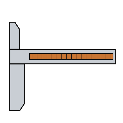
The beam is a metal bar with the fixed outside and inside jaws at one end, a wide shallow channel in its face and a second channel along its back. Fix the scale permanently into the face channel, copper up. The patent allows etching before or after this step. Not given: the metal, the dimensions and how the scale is fixed. Ours: epoxy.
Àwọn ohun èlò fún ìgbésẹ̀ yìí:
 Ọ̀pá kálípà1 with integral jaws
 Ìlẹ̀mọ́ epoxy ẹ̀yà méjì (tí ń le kíákíá)1 a little
Àwọn irinṣẹ́ tí a nílò:
 Ìwọ̀n tí a kò mọ̀
3
3
Fit the parts to the circuit
Fit the parts to the circuit
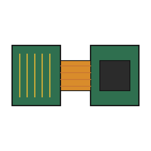
The circuit is one folded piece: a double-sided slider board joined by a flexible hinge to a circuit board. Its bottom face has two pickup electrodes, 0.750 x 0.110 inch and 0.0625 inch apart. On each side of them is an interdigitated transmitter array: fingers 0.115 inch long on 0.025 inch spacing, opening to 0.0375 inch at the centre. On the circuit board, solder or wire-bond the two chips: an NEC uPD7503 3 V processor (768 bits RAM, 2 kB ROM) and a CMOS gate array. Then fit the LCD, the 100 kHz crystal, the integrating capacitor and the MODE and SET buttons. Not given: the processor's program. Ours: a capacitor from a kit.
Àwọn ohun èlò fún ìgbésẹ̀ yìí:
 Pátákó àyíká líle-rírọ̀1 slider board + circuit board
 IC2 uPD7503 CPU, CMOS gate array
 Pánẹ́ẹ̀lì LCD oní-apá1 5 digits
 Kírísítà quartz1 100 kHz
 Àkójọpọ̀ Capacitor1 one integrating capacitor
 Bọ́tìnì ìtẹ̀2 MODE, SET
 Wáyà Sọ́ldà1 a little
Àwọn irinṣẹ́ tí a nílò:
 Irin ìsúdì
4
4
Build the slide
Build the slide
The slide frame wraps the back and edges of the beam and carries the movable jaws. Fix it to the depth rod, which runs in the back channel of the beam; the rod's free end is the depth gauge. Put the moulded plastic housing between the frame ends. Fasten two metal wear strips under the slider board, one on each side of the scale. They ride on the beam and connect the board's copper to it. Not given: the metal and sizes.
Àwọn ohun èlò fún ìgbésẹ̀ yìí:
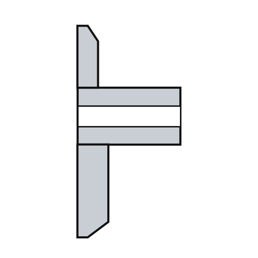 Férémù ìyọ̀1 with jaws
 Irin tí a kò mọ̀1 depth rod and two wear strips
 Àpótí ìyọ̀1 ẹyọ
Àwọn irinṣẹ́ tí a nílò:
Ìwọ̀n tí a kò mọ̀ Ìdìpọ̀ sìkírúdáìfà tí ó péye
5
5
Assemble and check
Assemble and check
Fold the circuit into the housing recess, slider board facing the scale, and screw it to the frame. The electrodes must lie parallel to the scale bars at every point of travel. Put the two 1.5 V cells (the patent says 'zinc oxide') in the battery pockets of the circuit. The display shows five digits, a ten-thousandths bar graph, a minus sign and 'mm', plus PEAK, LOW, HIGH and LIMIT. Ours: check the reading against a vernier caliper.
Àwọn ohun èlò fún ìgbésẹ̀ yìí:
 Skurú ẹ̀rọ2 ẹyọ
 Bátírì bọ́tìnnì fóltì 1.52 ẹyọ
Àwọn irinṣẹ́ tí a nílò:
Ìdìpọ̀ sìkírúdáìfà tí ó péye Kálípà Fáníà
Àwọn ohun-èlò
15- 1 strip, length of the beamÀyè
- 1 with integral jawsÀyè
- 1 a littleÀyè
- 1 slider board + circuit boardÀyè
- 2 uPD7503 CPU, CMOS gate arrayÀyè
- 1 5 digitsÀyè
- 1 100 kHzÀyè
- 1 one integrating capacitorÀyè
- Àyè
- 1 a littleÀyè
- 1 with jawsÀyè
- 1 depth rod and two wear stripsÀyè
- 1 ẹyọÀyè
- 2 ẹyọÀyè
- Àyè
Àwọn irinṣẹ́ tó nílò
7- 2 vendors sell this, none ship to you yetÀyè
- Àyè
Àwọn Ohun Èlò Ìtọ́nisọ́nà Tí A So Pọ̀

Ìtọ́nisọ́nà yìí ń ṣe

Blueprint tó jọra
Àwọn blueprint wọ̀nyí pín ìmọ̀ — ọ̀nà, ohun-èlò tàbí ìlànà
CC0 Àgbègbè Gbogbogbò
Blueprint yìí ti jáde lábẹ́ CC0. O lè ṣe àdàkọ, yí padà, pín, àti lò láìsí ìyọ̀ǹda.
Ṣàtìlẹ́yìn Olùṣẹ́dá nípa rírà àwọn ọjà nipasẹ̀ Blueprint wọn Ẹ̀san Olùṣẹ́dá tí àwọn Olùtajà gbé kalẹ̀, tàbí ṣẹ̀dá àtúnṣe tuntun ti Blueprint yìí kí o sì fi sínú Blueprint rẹ gẹ́gẹ́ bí ìsopọ̀ láti pín owó-wíwọlé.