Ìfọwọ́sowọ́pọ̀
IṢẸ́ ỌNÀ
ẸWÀ ÀTI ÌLERA
IṢẸ́ ỌWỌ́
ÀṢÀ ÀTI ÌTÀN
ÌṢERÉ
ÀYÍKÁ
OÚNJẸ ÀTI OHUN MÍMU
REVERSE ENGINEERING
SÁYẸ́ǸSÌ
ERÉ ÌDÁRAYÁ
ÌMỌ̀-Ẹ̀RỌ
ÀWỌN OHUN WÍWỌ̀

Pocket Morse Code Learning Board - v.1
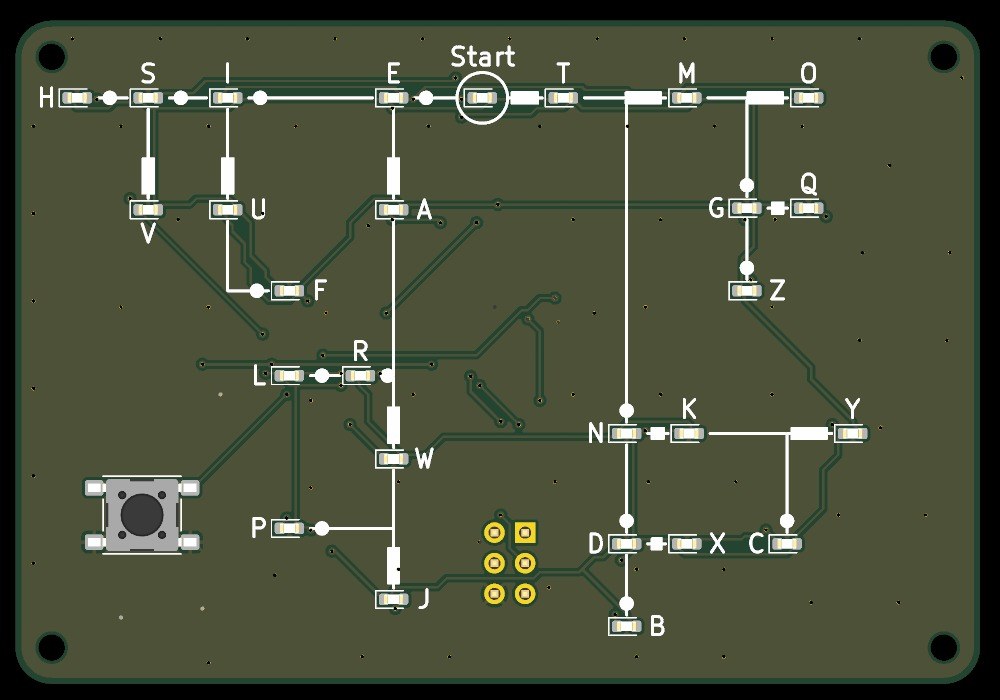
A pocket board, 80 x 55 mm, that teaches you to read Morse code. Its front is Dave Nathanson's Morse decoding chart: from Start, dots run one way and dashes the other, and every letter sits where its dots and dashes lead. Here every letter has its own LED. Press the key short for a dot and long for a dash, and the LED of the letter you have reached lights; pause, and it blinks.
It runs on one CR2032 coin cell and sleeps between uses. The board was drawn with Youblob's Draw PCB, and its checks pass, but it has not been built yet.
Ilọsíwájú
About 1 day, plus board delivery
Ìlànà
1
1
LED current and keying speed
LED current and keying speed
Ń ṣí ìwé Jupyter…
2
2
The code it decodes
The code it decodes
This board reads the International Morse code letters as ITU-R M.1677-1 gives them.
3
3
Read the chart
Read the chart
Dave Nathanson (KG6ZJO) drew his decoding chart in 2010: "Start with your finger at "Start Here". Then move your finger to track the Morse dots & dashes. You will arrive at the correct letter!" On this board the LEDs do the tracking. ITU-R M.1677-1: "A dash is equal to three dots."
4
4
The schematic
The schematic
ATmega328P on its internal 8 MHz clock, straight from the coin cell; 27 LEDs charlieplexed on PC0-PC5 through six 330 Ω resistors; the key on INT0; a 2x3 ISP footprint.
Ń gbé olùwò KiCanvas wọlé...
Olùwò Àpẹrẹ PCB Akọ́ṣẹ́mọṣẹ́
5
5
The board
The board
Two layers, 80 x 55 mm. The chart, LEDs and key on the front; the chip, resistors, capacitors and cell holder on the back.
Ń gbé olùwò KiCanvas wọlé...
Olùwò Àpẹrẹ PCB Akọ́ṣẹ́mọṣẹ́
6
6
Order the board
Order the board
Open the board in KiCad and plot Gerber and drill files (File > Fabrication Outputs). Order a two-layer board, 1.6 mm thick, from any board maker that takes Gerbers.
Àwọn ohun èlò fún ìgbésẹ̀ yìí:
 Àwo PCB1 ẹyọ
Àwọn irinṣẹ́ tí a nílò:
 Kọ̀ǹpútà Tí Ó Ní Arduino IDE
7
7
Solder the parts
Solder the parts
Back first: paste and reflow U1, R1-R7, C1-C3 and the cell holder BT1 with hot air. Then the front: the 27 red LEDs D1-D27 with pad 1 (cathode) as the board's assembly drawing shows, and the key SW1. Leave J1 empty. Clean off the flux, then test each LED's direction with the meter's diode test.
Àwọn ohun èlò fún ìgbésẹ̀ yìí:
 Microcontroller ATmega328P1 ẹyọ
 LED chip27 ẹyọ
 Rẹ́sístọ̀ chip7 ẹyọ
 Kápásítọ̀ seramiki chip3 ẹyọ
 Bọ́tìnì ìtẹ̀1 ẹyọ
 Ibi ìmú bátìrì1 ẹyọ
 Ìpara ìwélé (láìní òjé)1 ẹyọ
 Wáyà Sọ́ldà1 ẹyọ
Àwọn irinṣẹ́ tí a nílò:
 Ibùdó àtúnṣe afẹ́fẹ́ gbígbóná
 Irin ìsúdì
 Ìdìmú tí orí rẹ̀ mú
 Fúlọ́ksì
 Dígí Ìgbéga
 Òǹwọ̀n iná mànàmáná onírúurú
 Ọtí Isopropyl 99 %
8
8
The firmware
The firmware
pocket_morse_decoder_az.ino: every timing is a named constant at the top of the sketch. Board in the Arduino IDE: Arduino Pro or Pro Mini, ATmega328P (3.3V, 8 MHz).
pocket_morse_decoder_az.inoarduino
9
9
Set the fuses and upload
Set the fuses and upload
Do not use Burn Bootloader: the Pro board setting expects a crystal, and this board has none. Hold an ISP programmer's 2x3 pins on J1 and set the internal 8 MHz clock: avrdude -c usbasp -p m328p -U lfuse:w:0xE2:m -U hfuse:w:0xD9:m -U efuse:w:0xFF:m. Then, in the Arduino IDE, use Sketch > Upload Using Programmer.
Àwọn irinṣẹ́ tí a nílò:
 Olùkọ ètò AVR ISPKọ̀ǹpútà Tí Ó Ní Arduino IDE
10
10
Print the back shell
Print the back shell
An open-front shell, 84.8 x 59.8 x 8.9 mm, with four standoffs for M2 screws, a slot to slide the cell out and a window under J1. PLA, 0.2 mm layers, 20 % infill, printed on its floor.
11
11
Fit the shell
Fit the shell
The shell leaves 5.0 mm for the back parts: measure your cell holder with a cell in it before you print. Check the holder's open side faces the board's left edge, where the shell's cell slot is. Slide in a CR2032 and screw the board into the shell with four M2 self-tapping screws.
Àwọn ohun èlò fún ìgbésẹ̀ yìí:
 Okùn PLA1 ẹyọ
 Ìdè-skúrù tí ń gé ọ̀nà ara rẹ̀4 ẹyọ
 Bátìrì owó ẹyọ CR20321 ẹyọ
Àwọn irinṣẹ́ tí a nílò:
 Ẹ̀rọ ìtẹ̀ 3D oníwàyà (FDM)
 Kálípà Fáníà
 Ìdìpọ̀ sìkírúdáìfà tí ó péye
12
12
Troubleshooting
Troubleshooting
Pocket Morse decoder troubleshooting.
Flow
Loading...
13
13
History and honest limits
History and honest limits
The chart is **Dave Nathanson**'s (KG6ZJO), drawn in 2010 and shared as copyleft; his post says it is a novel way to decode by following a path. The letter codes are ITU-R M.1677-1's. The board, sizes, parts and timings are ours, drawn with Youblob's Draw PCB: its ERC and DRC pass with no errors and every LED's wiring was checked against the firmware by script, but it has not been built, flashed or tested.
Àwọn ohun-èlò
12- 1 ẹyọÀyè
- Àyè
- 27 ẹyọÀyè
- 7 ẹyọÀyè
- Àyè
- Àyè
- Àyè
- Àyè
- 1 ẹyọÀyè
- 1 ẹyọÀyè
- Àyè
- Àyè
Àwọn irinṣẹ́ tó nílò
12- 2 vendors sell this, none ship to you yetÀyè
- Àyè
- Àyè
- Àyè
Àwọn fáìlì àpẹrẹ
1Ìtọ́nisọ́nà yìí ń ṣe

Blueprint tó jọra
Àwọn blueprint wọ̀nyí pín ìmọ̀ — ọ̀nà, ohun-èlò tàbí ìlànà

CC0 Àgbègbè Gbogbogbò
Blueprint yìí ti jáde lábẹ́ CC0. O lè ṣe àdàkọ, yí padà, pín, àti lò láìsí ìyọ̀ǹda.
Ṣàtìlẹ́yìn Olùṣẹ́dá nípa rírà àwọn ọjà nipasẹ̀ Blueprint wọn Ẹ̀san Olùṣẹ́dá tí àwọn Olùtajà gbé kalẹ̀, tàbí ṣẹ̀dá àtúnṣe tuntun ti Blueprint yìí kí o sì fi sínú Blueprint rẹ gẹ́gẹ́ bí ìsopọ̀ láti pín owó-wíwọlé.