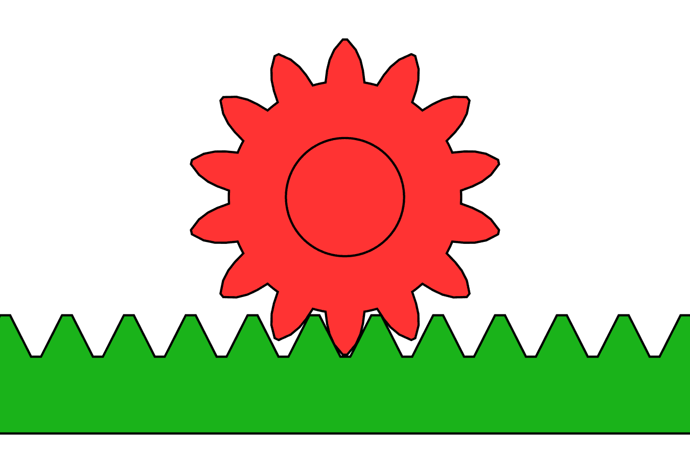


Rack and Pinion
Ìlànà
Work out the numbers before cutting anything
Work out the numbers before cutting anything
Module and tooth count fix every dimension that follows.
- Choose module 2 — tooth pitch is then π × 2 = 6.28 mm.
- For a 20-tooth pinion, pitch diameter = module × teeth = 40 mm.
- Travel per pinion revolution = π × 40 = 125.7 mm.
- Centre distance from pinion axis to rack pitch line = pitch radius = 20 mm.
- Write these four numbers on the workpiece.
Modern build spec (derived). Module 2 is chosen because it is the smallest common metric size with teeth robust enough to cut in aluminium or buy cheaply in steel, and because 20 mm centre distance is easy to hold accurately in plywood.
Everything downstream is a consequence of these four numbers. Write them down — the commonest failure in this build is drilling the pinion shaft hole at a guessed height and discovering the teeth either bottom out or barely touch.Àwọn ohun èlò fún ìgbésẹ̀ yìí:
 Pìláwọ́ọ̀dù Bíṣì Baltiki1 ewé
Àwọn irinṣẹ́ tí a nílò:
 Òṣùwọ̀n Kálípà Díjítà Ìnṣì 6
 Igun Àpapọ̀
Mount the rack dead straight
Mount the rack dead straight
Any bow in the rack becomes a periodic tight spot in the travel.
- Cut the baseplate 400 × 160 mm from 18 mm ply.
- Lay the rack along a scribed line and clamp it.
- Drill through the rack's mounting holes into the base at 3.3 mm, one hole at a time, fitting a screw before drilling the next.
- Fix with M4 × 20 socket head cap screws × 5 and M4 flat washers × 5.
- Check straightness by sighting along the tooth tips.
Àwọn ohun èlò fún ìgbésẹ̀ yìí:
 Ìṣọ Onípọ̀n Orí Sokẹ́ẹ̀tì5 ẹyọ
 Wáṣà Pẹrẹsẹ5 ẹyọ
Àwọn irinṣẹ́ tí a nílò:
 Ẹ̀rọ Ìlùkòkò Aláìlókùn
 Àkójọ Orí Ìlùkòkò
 Àkójọ Kọ́kọ́rọ́ Onígun Mẹ́fàIgun Àpapọ̀
Build the pinion bearing block with adjustment
Build the pinion bearing block with adjustment
Do not drill a fixed hole — build in the ability to correct.
- Cut a bearing block 80 × 60 mm from 18 mm ply.
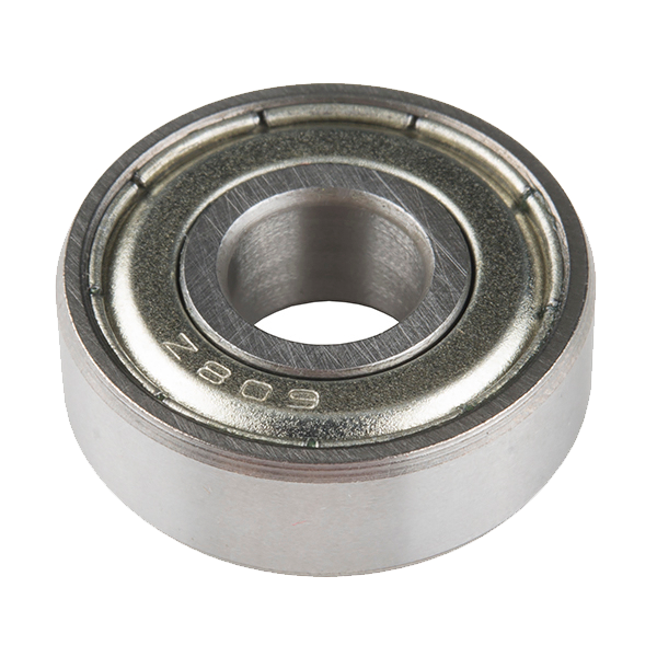
- Bore a 22 mm recess to take a 608 bearing, positioned so the pinion axis sits 20 mm above the rack pitch line.
- Drill the block's two mounting holes as SLOTS, 4.2 mm wide and 6 mm long, running vertically.
- Mount with M4 × 30 socket head cap screws × 2, M4 flat washers × 4 and M4 hex nuts × 2, left finger tight.
What period machines did: scraped and shimmed the bearing pedestal to set mesh depth. Modern build spec (derived): slotted mounting holes give the same adjustment with a hex key, and the 608 bearing removes the bronze bush that would otherwise need fitting and oiling.
The slots are the whole point of this step. Mesh depth is a fit you set by feel with the mechanism assembled, and a fixed hole gives you exactly one attempt at getting it right.Àwọn ohun èlò fún ìgbésẹ̀ yìí:
 Ball Bearing - Non-Flanged (8mm Bore, 22mm OD)2 ẹyọÌṣọ Onípọ̀n Orí Sokẹ́ẹ̀tì2 ẹyọWáṣà Pẹrẹsẹ4 ẹyọ
 Nọ́ọ̀tì Onígun Mẹ́fà2 ẹyọ
Àwọn irinṣẹ́ tí a nílò:
Ẹ̀rọ Ìlùkòkò AláìlókùnÀkójọ Orí Ìlùkòkò Ayùn Kópìngì
 Àkójọ ÌfáÒṣùwọ̀n Kálípà Díjítà Ìnṣì 6
Set mesh depth by feel, then lock it
Set mesh depth by feel, then lock it
This is the adjustment the whole build exists to teach.
- With the screws finger tight, press the pinion fully into mesh and run it along the rack.
- Back the block off until the pinion turns freely with a barely perceptible rock.
- Run the pinion along the full rack length, listening for tight spots.
- Tighten both M4 screws evenly and re-check.
- Fit the drive handle to the pinion shaft with an M5 × 16 socket head cap screw and M5 flat washer.
Àwọn ohun èlò fún ìgbésẹ̀ yìí:
Wáṣà Pẹrẹsẹ1 ẹyọ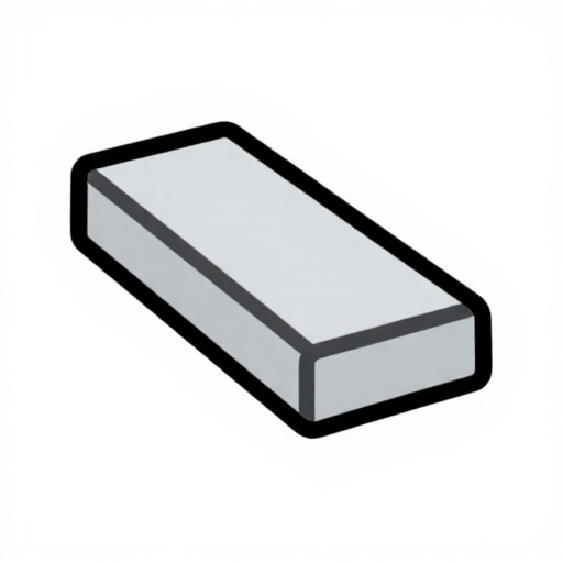 Ọ̀pá pẹlẹbẹ ti aluminium1 ẹyọ
Àwọn irinṣẹ́ tí a nílò:
Àkójọ Kọ́kọ́rọ́ Onígun Mẹ́fàÒṣùwọ̀n Kálípà Díjítà Ìnṣì 6Àkójọ ÌfáMeasure the ratio, and history
Measure the ratio, and history
Verify the arithmetic against the hardware.
- Mark a start position on the rack and measure it with the caliper.
- Turn the pinion exactly one revolution.
- Measure again — the difference should be 125.7 mm.
- Repeat over five revolutions and divide, to average out your reading error.
Agreement within a millimetre over five turns confirms both your module arithmetic and your mesh setting. A consistent shortfall means the pinion is riding high in the teeth.
History. Rack and pinion drives appear in mining and mill machinery well before they reached vehicles. The Riggenbach and Abt rack railway systems of the 1860s and 1880s used a toothed rail between the running rails so locomotives could climb gradients far too steep for adhesion alone — the same mechanism at enormous scale. In steering, rack and pinion gradually replaced recirculating-ball boxes through the twentieth century because it has fewer joints between the wheel and the road, and therefore less lost motion.
What it trades against its siblings: the screw jack gives enormous force multiplication and holds position when released, but moves slowly and wastes most of its input to friction. The worm reducer gives a large ratio in one step and can be made self-locking. The rack gives unlimited travel and high efficiency with NO self-locking at all — release the handle under load and it drives itself backwards. That property is exactly why a rack steers a car and a screw lifts it.
The honest limit: travel costs material. Doubling the stroke means doubling the length of an accurately toothed bar, and the rack must be supported along its whole length. For long strokes the cost grows linearly where a screw or a cable does not, which is why very long travels usually use something else.
Àwọn irinṣẹ́ tí a nílò:
Òṣùwọ̀n Kálípà Díjítà Ìnṣì 6Àwọn ohun-èlò
7- Àyè
- Àyè
- 9 ẹyọÀyè
- 2 ẹyọ$1.26
- 2 ẹyọÀyè
- 1 ẹyọÀyè
- Àyè
Àwọn irinṣẹ́ tó nílò
7- Àyè
- 1 vendor sell this, none ship to you yetÀyè
- Àyè
- Àyè
Blueprint tó jọra
Àwọn blueprint wọ̀nyí pín ìmọ̀ — ọ̀nà, ohun-èlò tàbí ìlànà

CC0 Àgbègbè Gbogbogbò
Blueprint yìí ti jáde lábẹ́ CC0. O lè ṣe àdàkọ, yí padà, pín, àti lò láìsí ìyọ̀ǹda.
Ṣàtìlẹ́yìn Olùṣẹ́dá nípa rírà àwọn ọjà nipasẹ̀ Blueprint wọn Ẹ̀san Olùṣẹ́dá tí àwọn Olùtajà gbé kalẹ̀, tàbí ṣẹ̀dá àtúnṣe tuntun ti Blueprint yìí kí o sì fi sínú Blueprint rẹ gẹ́gẹ́ bí ìsopọ̀ láti pín owó-wíwọlé.