IṢẸ́ ỌNÀ
ẸWÀ ÀTI ÌLERA
IṢẸ́ ỌWỌ́
ÀṢÀ ÀTI ÌTÀN
ÌṢERÉ
ÀYÍKÁ
OÚNJẸ ÀTI OHUN MÍMU
REVERSE ENGINEERING
SÁYẸ́ǸSÌ
ERÉ ÌDÁRAYÁ
ÌMỌ̀-Ẹ̀RỌ
ÀWỌN OHUN WÍWỌ̀

The Rod-Lens Endoscope
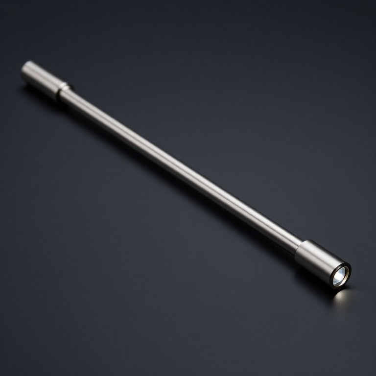
To see inside the body through a tube a few millimetres across, you must relay an image along that tube without losing it. The classical way is a train of small lenses held in rings, with long air gaps between them. It works and it is dim, because a narrow tube full of air gaps collects very little light and every mounting ring eats into the aperture.
In 1959 Harold Hopkins turned the arrangement inside out. Instead of thin glass lenses separated by long air spaces, he used long glass rods separated by thin air spaces. The optical function is the same — the surfaces still do the work — but now the tube is almost entirely filled with glass.
Two things follow. First, the space between surfaces is glass rather than air, and the light-gathering capacity of an optical system scales with the square of the refractive index of the medium it passes through, so filling the gap with glass multiplies throughput before anything else changes. Second, and in practice larger, a glass rod supports itself. It needs no mounting ring, so it can be as wide as the tube, while a thin lens must be held at its rim by hardware that steals aperture. Hopkins reported the combined gain over the systems he replaced as very large indeed, and the instrument went from a dim curiosity to something a surgeon could work by.
You will build both relays side by side on an optical bench and measure the difference yourself, rather than take the number on trust.
Ilọsíwájú
7 hours
Ìlànà
1
1
Build the classical relay first
Build the classical relay first
Do the old design first, because the comparison is the point and you need the baseline honestly made.
Set up a relay of small plano-convex lenses on a rail inside a tube. Each pair of lenses re-images the previous image plane onto the next, so the picture is carried down the tube in a series of hops. Place a resolution target at the object end and an eyepiece at the other.
The two things to get right are spacing and stops. Space the lenses so each intermediate image falls between pairs, not on a glass surface, or every scratch and speck on that surface joins the picture permanently. And note carefully where the beam is widest — the aperture stop of the whole system is wherever the beam is most nearly filling the available diameter, and in a small-lens relay that is almost always at a lens rim rather than anywhere you chose.
Measure two numbers before moving on. Photograph the target through the eyepiece with fixed camera settings and record the image brightness. Then find the finest target group still resolvable. Write both down. Everything in step 4 is a comparison against these.
Àwọn ohun èlò fún ìgbésẹ̀ yìí:
 Àkójọ lẹ́ńsì pẹlẹbẹ-ìbọ̀1 ìtò
 Páìpù aluminium1 metre
 Àwòrán ìdánwò ìtúmọ̀ USAF 19511 ẹyọ
Àwọn irinṣẹ́ tí a nílò:
 Ọ̀nà pẹpẹ optiki
 Ohun ìgbé lórí pẹpẹ optiki
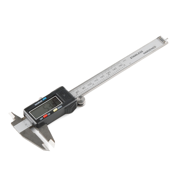 Digital Calipers - 152.4 mm
 Mákírósíkóòpù Oní Nọ́ńbà
2
2
Where the light actually goes
Where the light actually goes
Ń ṣí ìwé Jupyter…
Àwọn irinṣẹ́ tí a nílò:
 Kọ̀ǹpútà Tábìlì
3
3
Build the rod relay and measure the gain
Build the rod relay and measure the gain
Cut rods from borosilicate or, better, from a higher-index glass if you can get it. Length is not critical to a millimetre but the two end faces must be flat, polished, and square to the axis — this is the lens grinding skill again, applied to a short cylinder, and the flatness matters more than anything else you will do today.
Grind a shallow convex curve onto the faces that need power, and leave flat those that do not. Work through the grits and finish on pitch with fine oxide. Check flatness by interference against a known flat if you have one, or by autocollimation off a mirror.
Assemble the rods into the same tube, at the same overall length, imaging the same target. Everything except the relay itself must be identical to step 1 or the comparison is worthless — same illumination, same eyepiece, same camera settings, same target distance.
Photograph and measure. Compare brightness against your step 1 baseline, and compare resolved target group. Expect a large brightness gain and also a resolution gain, the second because the wider aperture reduces diffraction as well as admitting more light.
If your measured gain is well below the notebook's prediction, the usual cause is that your rod end faces are not flat and are scattering. Look at the bright field through the relay with no target: scattered light shows as a milky haze, and the haze is your polish quality made visible.
Àwọn ohun èlò fún ìgbésẹ̀ yìí:
 Ọ̀pá Gíláàsì Borosilicate6 ẹyọ
 Ìṣù èérún ìlọ̀ silicon carbide1 ìtò
 Ohun ìdán ti cerium oxide250 gramPáìpù aluminium1 metre
Àwọn irinṣẹ́ tí a nílò:
Ọ̀nà pẹpẹ optikiOhun ìgbé lórí pẹpẹ optikiMákírósíkóòpù Oní Nọ́ńbà Prism gíláàsì (ẹgbẹ́ dọ́gba)
4
4
Add cold light, and read the limit
Add cold light, and read the limit
There is a second half to the instrument that is easy to forget. A relay this bright is useless without illumination at the far end, and a lamp small enough to fit down the tube gets hot enough to burn tissue.
The answer is to leave the lamp outside and pipe the light in along a bundle of fibres running beside the relay. The heat stays at the lamp. This is why the modern instrument is called a cold light source, and it is the other half of the same insight — glass carries light better than air over distance.
Add a fibre bundle alongside your relay, illuminate from a lamp at the bench end, and note that you can now hold the far end of the instrument against your palm indefinitely. That is the whole point.
Where this stops. You have built two optical relays, measured the throughput difference, and separated the contributions to it. That is real optical engineering and it transfers to any long imaging path — borescopes for engines, inspection of castings, periscopes. It is not a medical endoscope. A clinical instrument must survive repeated sterilisation without the cement between elements clouding or the seals admitting fluid, must be leak-tested before every use because a breach admits contamination into the next patient, has a specified field of view and angle of view that the operator relies on for orientation, and is used by someone trained in where the instrument may and may not be advanced. Point yours down a length of pipe, into an engine, or at a casting. Not into a person or an animal.
Àwọn ohun èlò fún ìgbésẹ̀ yìí:
 Ìdì okùn ìmọ́lẹ̀1 metre
 Orísun ìmọ́lẹ̀ LED1 ẹyọ
Àwọn irinṣẹ́ tí a nílò:
Ọ̀nà pẹpẹ optikiOhun ìgbé lórí pẹpẹ optiki Òṣùwọ̀n Oníṣirò Díjítà Ìpele Yàrá Ìwádìí
Àwọn ohun-èlò
8- Àyè
- 1 metreÀyè
- Àyè
- Àyè
- Àyè
- 250 gramÀyè
- 1 metreÀyè
- 1 ẹyọÀyè
Àwọn irinṣẹ́ tó nílò
7- Digital Calipers - 152.4 mmìdá 10%$14.06
Blueprint tó jọra
Àwọn blueprint wọ̀nyí pín ìmọ̀ — ọ̀nà, ohun-èlò tàbí ìlànà
CC0 Àgbègbè Gbogbogbò
Blueprint yìí ti jáde lábẹ́ CC0. O lè ṣe àdàkọ, yí padà, pín, àti lò láìsí ìyọ̀ǹda.
Ṣàtìlẹ́yìn Olùṣẹ́dá nípa rírà àwọn ọjà nipasẹ̀ Blueprint wọn Ẹ̀san Olùṣẹ́dá tí àwọn Olùtajà gbé kalẹ̀, tàbí ṣẹ̀dá àtúnṣe tuntun ti Blueprint yìí kí o sì fi sínú Blueprint rẹ gẹ́gẹ́ bí ìsopọ̀ láti pín owó-wíwọlé.