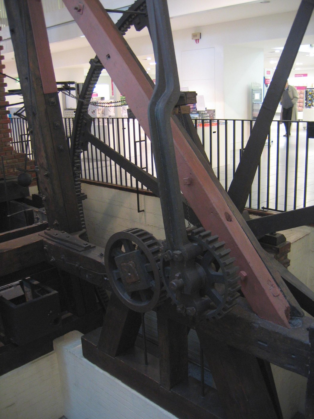


Rotative Beam Engine
Every steam engine before this one pumped. Up and down, a beam rocking, water lifted out of a mine — useful, and useless for anything that needs a turning shaft. Making steam drive a rotation is what let engines out of the mine and into the mill.
Three problems had to be solved together. Convert reciprocating motion to rotary — around a crank patent somebody else held. Guide the piston rod in a straight line while the beam end swings in an arc. And keep the speed steady as the load changes.
Watt's answers were the sun-and-planet gear, the parallel motion linkage and the centrifugal governor. Build the model and all three problems become obvious in the first minute of cranking — which is the fastest way to understand why they were worth patenting.
Ìlànà
Build it as a hand-driven model
Build it as a hand-driven model
This is a working model of the mechanism, turned by hand or a small motor — no steam, no boiler, no pressure anywhere. The linkages are the subject; the power source is not.
Make a rigid frame
Make a rigid frame
Build an upright frame on a baseboard tall enough to carry the beam above the cylinder. Any flex in the frame turns into slop in every linkage hanging off it.
Àwọn ohun èlò fún ìgbésẹ̀ yìí:
 Pátákó Igi Líle2 ẹyọ
Pivot the beam at its centre
Pivot the beam at its centre
Mount a beam 400 mm long on a free central pivot at the top of the frame. It must rock with almost no friction — a stiff beam pivot masks everything downstream.
Fit a cylinder and piston rod
Fit a cylinder and piston rod
Fit a tube as the cylinder under one end of the beam, with a rod sliding in it. In a real engine the rod must stay in line with the cylinder or it wears the bore oval and leaks.
Àwọn ohun èlò fún ìgbésẹ̀ yìí:
 Ọ̀pá Bàbà Ofeefee1 ẹyọ
Prove the problem before solving it
Prove the problem before solving it
Connect the rod straight to the beam end with one pin and rock the beam. The rod is dragged sideways because the beam end travels an arc while the rod must travel a line. Feel that binding — it is what the next step exists to fix.
Build the parallel motion linkage
Build the parallel motion linkage
Add Watt's linkage: a four-bar arrangement of the beam end, two links and a fixed anchor, proportioned so the connection point traces a near-straight line over its working range.
Àwọn irinṣẹ́ tí a nílò:
 Ìdíwọ̀n
Measure how straight it actually is
Measure how straight it actually is
Clip a pencil to the connection point and let it draw on card as the beam rocks its full travel. Measure the deviation from a ruled line — a few tenths of a millimetre over a long stroke is a good result, and it is approximately straight, never exactly.
Àwọn ohun èlò fún ìgbésẹ̀ yìí:
 Bébà Líle1 ewé
Fit a flywheel on a shaft
Fit a flywheel on a shaft
Mount a heavy disc on a free-running shaft at the far end. The flywheel carries the engine through the dead points where the beam reverses and no force is being delivered.
Make the sun and planet gears
Make the sun and planet gears
Fix one gear — the sun — to the flywheel shaft, and fasten a second gear of the same size — the planet — rigidly to the end of the connecting rod so that it cannot rotate on its own pin. That fixed planet is the whole trick.
Constrain the planet to orbit the sun
Constrain the planet to orbit the sun
Add a link between the two gear centres to hold them in mesh while the planet swings around the sun. The connecting rod pushes the planet around and the meshing teeth turn the sun.
Count the turns per stroke
Count the turns per stroke
Mark the flywheel and count its revolutions per full beam cycle. With equal gears the sun turns twice per orbit — the arrangement gives two flywheel revolutions per engine stroke, where a plain crank gives one.
Compare against a plain crank
Compare against a plain crank
Swap in a simple crank and turn it. It does the same job with fewer parts and less friction. The sun-and-planet is not the better mechanism — it existed to get around a patent, and knowing that is the point of the comparison.
Add a governor drive
Add a governor drive
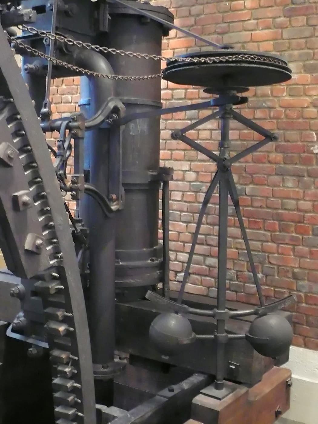
Belt a small centrifugal governor off the flywheel shaft and link its sleeve to a throttle flap. Now the model has all three of Watt's mechanisms working together.
Run it and load it
Run it and load it
Turn the flywheel steadily and press a finger on it to simulate load. Watch the beam, the straight-line linkage and the governor respond together. That combination — rotation, guided rod, self-regulated speed — is what a mill actually needed.
History & Context
History & Context
The patent that forced an invention. The obvious way to turn reciprocating motion into rotation is a crank and flywheel — and James Pickard patented exactly that combination in 1780. Boulton and Watt needed a way round it. The sun-and-planet gear was invented by William Murdoch, an employee of the firm, and patented by Watt in October 1781. It had a commercial life of about twenty years and was largely dropped after Pickard's crank patent expired in 1794, when Boulton and Watt moved most new engines to plain cranks. The mechanism is a monument to patent law rather than to engineering necessity — and it does have one genuine advantage, the doubled flywheel speed.
Parallel motion. The beam end swings through an arc; the piston rod must move in a straight line. Watt's linkage traces a very close approximation to a straight line over the working stroke — approximate, always, but close enough that the rod does not bind. Watt is said to have been prouder of it than of anything else he devised, which for the man who separated the condenser is a striking judgement. Parallel motion and the sun-and-planet gear appear together on a drawing dated November 1784.
Single-acting, then double. The early rotative engines were single-acting: steam pushed the piston one way and the beam and flywheel returned it. Conversion to double action — steam admitted alternately to both sides of the piston — roughly doubled the power from the same cylinder.
Why this engine changed the shape of industry. A pumping engine has to sit next to what it drains. A rotative engine drives a shaft, and a shaft drives a whole mill through belts and gearing. That is what took manufacturing off rivers and put it wherever coal could be delivered — and it is the single mechanical change most directly behind the geography of the Industrial Revolution.
Àwọn ohun-èlò
3- 2 ẹyọÀyè
- 1 ẹyọÀyè
- 1 ewéÀyè
Àwọn Ohun Èlò Ìtọ́nisọ́nà Tí A So Pọ̀
CC0 Àgbègbè Gbogbogbò
Blueprint yìí ti jáde lábẹ́ CC0. O lè ṣe àdàkọ, yí padà, pín, àti lò láìsí ìyọ̀ǹda.
Ṣàtìlẹ́yìn Olùṣẹ́dá nípa rírà àwọn ọjà nipasẹ̀ Blueprint wọn Ẹ̀san Olùṣẹ́dá tí àwọn Olùtajà gbé kalẹ̀, tàbí ṣẹ̀dá àtúnṣe tuntun ti Blueprint yìí kí o sì fi sínú Blueprint rẹ gẹ́gẹ́ bí ìsopọ̀ láti pín owó-wíwọlé.