Collaboration
ART
BEAUTY & WELLNESS
CRAFT
CULTURE & HISTORY
ENTERTAINMENT
ENVIRONMENT
FOOD & DRINKS
REVERSE ENGINEERING
SCIENCES
SPORTS
TECHNOLOGY
WEARABLES
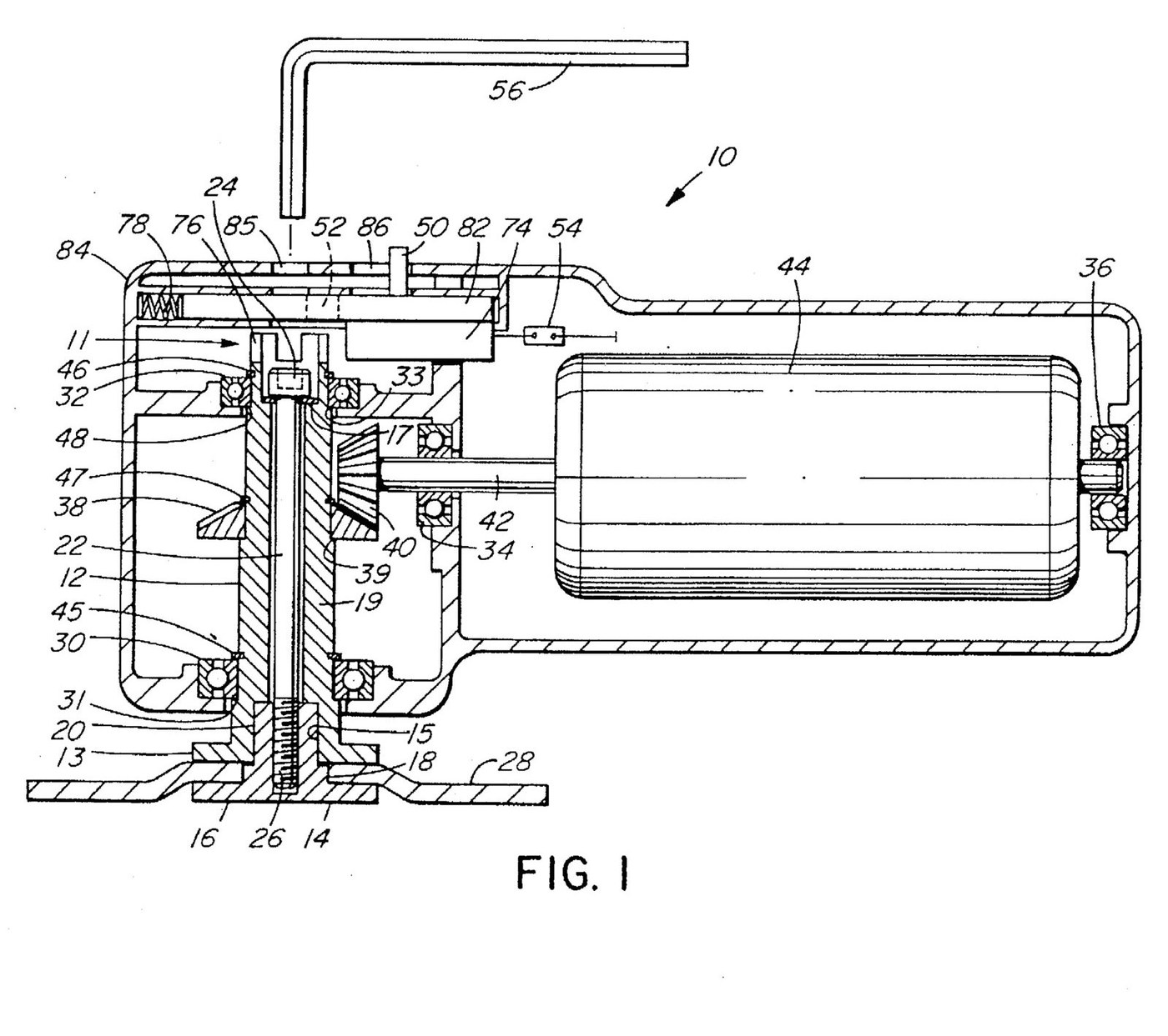


Angle Grinder: Reversible, with a Hollow Arbour and a Top Arbour Lock (Turley, US 5,718,621)
An angle grinder spins a disc at right angles to its motor: a bevel gear on the motor shaft turns a bevel gear on an upright arbour. E. M. Turley (US 5,718,621, 1998) makes the arbour hollow. A bolt runs down through it into a hexagonal coupling piece that drives the disc and clamps it against the arbour's flange, so the motor can run either way without loosening the disc.
To change the disc, a sliding lock piece on top locks the arbour, opens a hole over the bolt head and switches the motor off in one move.
Source: E. M. Turley, "Reversible Angle Grinder with Top Arbour Lock", US Patent 5,718,621 (filed 1996, granted 1998). Picture: its Fig. 1.
Advanced
Unknown
Instructions
1
1
Read Turley
Read Turley
"The angle grinder according to the preferred embodiment of the invention includes a reversible motor driving a hollow arbour via a right angle bevel gear arrangement. The arbour has a right angle flange at its bottom. The flange abuts against one side of the disk tool."
2
2
Turn the hollow arbour
Turn the hollow arbour
Turn an arbour hollow all through, with three outside shoulders (lower, middle and upper) for the two bearings and the bevel gear, and grooves above each for a snap ring. At the bottom, enlarge the bore into a hexagonal recess ending in a right-angle flange. At the top, enlarge the bore so the bolt head sits below the rim, and cut four equally spaced square notches (crenellations) in the rim. Sizes and metal are not given.
Materials for this step:
 Unknown Metal1 arbour
Tools needed:
 Metal Lathe
 Milling Machine
 Files (Hand File)
 Unknown Dimensions
3
3
Make the coupling piece and bolt
Make the coupling piece and bolt
Make a coupling piece: a hexagonal upper part that fits the arbour's recess, a round pilot that fits the standard centre hole of commercial grinding discs, and a right-angle flange at its base. Bore and tap it from the top, closed at the bottom. Make a retaining bolt long enough to run from the arbour's top down into the coupling piece, threaded at its lower end (Fig. 1 draws a socket in its head).
Materials for this step:
Unknown Metal1 coupling pieceUnknown Metal1 retaining boltTools needed:
Metal LatheMilling Machine Tap and Die SetUnknown Dimensions
4
4
Cut the bevel gears
Cut the bevel gears
Cut two bevel gears with teeth at forty-five degrees (equal gears for a right-angle drive): one fixed on the arbour against its middle shoulder, one on the front end of the motor shaft. Tooth count and metal are not given.
Materials for this step:
Unknown Metal2 bevel gearsTools needed:
Milling Machine Bevel Gear CutterUnknown Dimensions
5
5
Assemble the drive
Assemble the drive
Mount a reversible electric motor in the housing, its shaft running back in a rear bearing and forward in a front bearing, the bevel gear on its front end. Set the arbour upright in two bearings at its lower and upper shoulders, the bevel gears meshing, with snap rings above the bearings and the gear. Drop the bolt down the arbour on a lock washer, fit the coupling piece from below and screw it on. Motor rating, housing material and how the bearings are held are not given.
Materials for this step:
 Electric Motor1 reversible
 Ball Bearing4 pieces
 Unknown Material1 housing
Tools needed:
 Hex Key Set
 Unknown Forming MethodUnknown Dimensions
6
6
Fit the arbour lock
Fit the arbour lock
Make a rectangular lock piece that slides in the housing top across the arbour head, with a lever up through a slot in the housing, a tool hole, and a square tang underneath that drops into a rim notch. A spring on its front face holds it back in the running position. Fix a two-contact power switch to its rear so the motor circuit is broken when the piece is slid into the locking position. Cut a hole in the housing top over the bolt head and a slot for the lever.
Materials for this step:
Unknown Metal1 lock piece Spring1 piece
 On/Off Switch1 piece
Tools needed:
Milling Machine Drill Press
 Drill Bit SetFiles (Hand File)
7
7
Change a disc
Change a disc
Push the lever forward: the tang locks the arbour, the switch cuts the motor and the tool hole sits over the bolt head. Unscrew the bolt from above with the key and pull the coupling piece; put the new disc on its pilot and screw it back up tight, so the disc is clamped between the arbour flange and the coupling flange. Let the lever spring back to run. Turley: a loose bolt cannot drop the disc, which rattles to warn you to tighten it.
Tools needed:
Hex Key SetMaterials
6- 1 lock piecePlaceholder
- 1 reversiblePlaceholder
- fromNOK 12.00
- 1 housingPlaceholder
- 1 piecePlaceholder
- 1 piecePlaceholder
Tools Required
10- Placeholder
- Placeholder
- Placeholder
- Placeholder
- Placeholder
- Placeholder
- Placeholder
- Placeholder
- Placeholder
- Placeholder
This blueprint makes

CC0 Public Domain
This blueprint is released under CC0. You are free to copy, modify, distribute, and use this work for any purpose, without asking permission.
Support the Maker by purchasing products through their Blueprint where they earn a Maker Commission set by Vendors, or create a new iteration of this Blueprint and include it as a connection in your own Blueprint to share revenue.