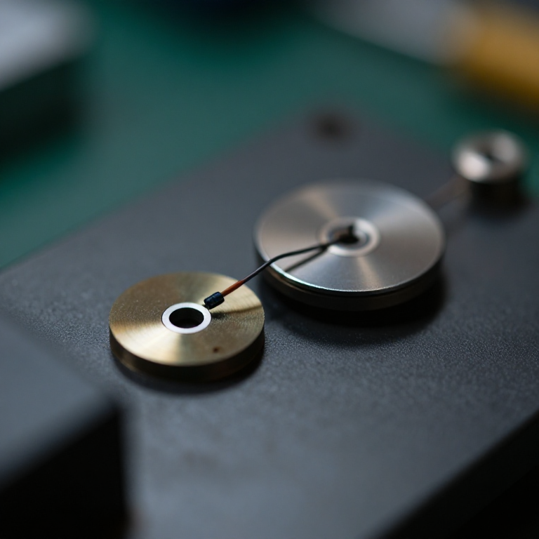


Moving-Coil Microphone
Instructions
Prove reciprocity with a loudspeaker first
Prove reciprocity with a loudspeaker first
Before building anything, demonstrate that a speaker already IS a microphone.
- Take a small loudspeaker and connect its terminals straight to an oscilloscope.
- Speak into the cone and watch the trace.
- Now connect the same speaker to an amplifier input and listen through headphones.
- Tap the cone and hear the thump.
It works, and it works reasonably well. Intercom systems have used a single speaker as both microphone and earpiece for decades, switching it between the two. The transducer does not know which direction it is being used in — this is electromagnetic reciprocity, and it is the reason this blueprint and the loudspeaker blueprint describe the same machine.
A large speaker makes a poor microphone mainly because its cone is heavy and its resonance is low. Everything that follows is about making the same motor with far less moving mass.Materials for this step:
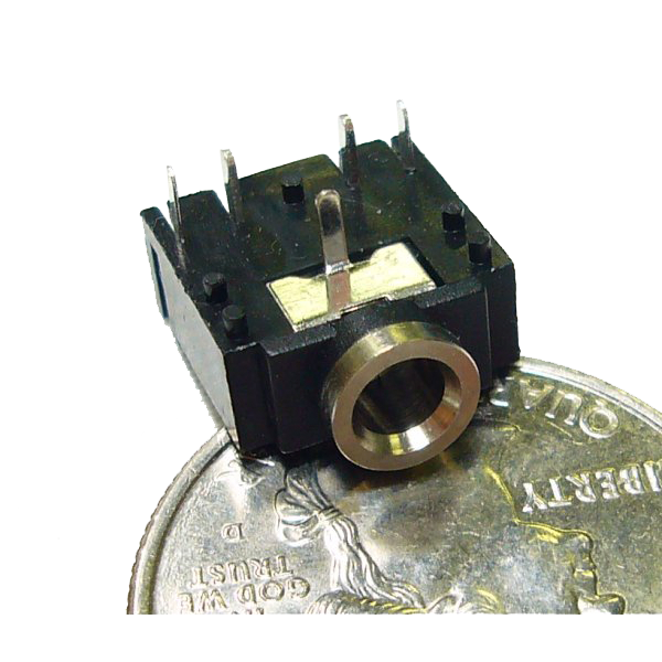 Audio Jack 3.5mm1 piece
Tools needed:
 Digital Oscilloscope (100MHz, 2-Channel)
 Digital Multimeter (Lab Grade)
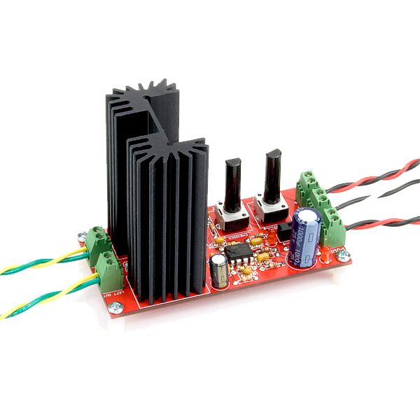 Audio Amplifier Kit - STA540
Wind a light coil and hang it in a magnetic gap
Wind a light coil and hang it in a magnetic gap
Low mass and a strong field are the two things that matter.
- Wind about 40 turns of very fine enamelled wire on a former of 15 mm diameter.
- Slide the former off — the coil should hold together with a spot of adhesive and weigh almost nothing.
- Build a magnetic circuit: a ring magnet with a central pole piece, leaving a narrow annular gap.
- Suspend the coil in that gap so it can move axially without touching either side.
- Attach a light mylar diaphragm to the coil.
The gap must be narrow and the coil must never touch. A narrow gap concentrates the flux, and output is proportional to flux density — but a coil rubbing on the pole piece produces a scraping noise and eventually jams. The suspension has to hold it centred while offering almost no resistance to axial motion, which is the whole mechanical design problem.
Fine wire and few turns. More turns gives more output but more mass, and mass costs treble. Every moving-coil microphone is a compromise struck at that point.Materials for this step:
 Enamelled Copper Wire1 roll
 Emergency Mylar Blanket1 piece
 Ferrite Bead Kit1 kit
Tools needed:
 Digital Caliper 6-Inch
 File SetDigital Multimeter (Lab Grade)
 Digital Kitchen Scale
Make it directional by controlling the rear entry
Make it directional by controlling the rear entry
A sealed capsule hears everything equally. Openings at the back create the pattern.
- Seal the capsule's rear completely and measure output as you walk a sound source around it — the response is nearly uniform.
- Now open small ports at the rear of the capsule.
- Repeat the circular measurement and plot it.
- Vary the port size and repeat.
Materials for this step:
 Cotton Muslin Cloth1 metre
 Graph Paper1 pad
Tools needed:
Digital Oscilloscope (100MHz, 2-Channel) DDS Signal Generator (1Hz-65MHz)Digital Caliper 6-Inch
 Cordless Drill/Driver (20V)
Test what it survives that a condenser will not
Test what it survives that a condenser will not
The case for the dynamic microphone is robustness, so test that specifically.
- Measure the output at a very high sound level close to a loud source and check the waveform for clipping.
- Breathe heavily on the capsule and listen for crackling.
- Leave it in a cold damp place for an hour and test again.
- Compare each result with the condenser capsule from the previous blueprint.
Tools needed:
Digital Oscilloscope (100MHz, 2-Channel)Digital Multimeter (Lab Grade) Cooking Thermometer (0-200°C)
One motor, two directions, and history
One motor, two directions, and history
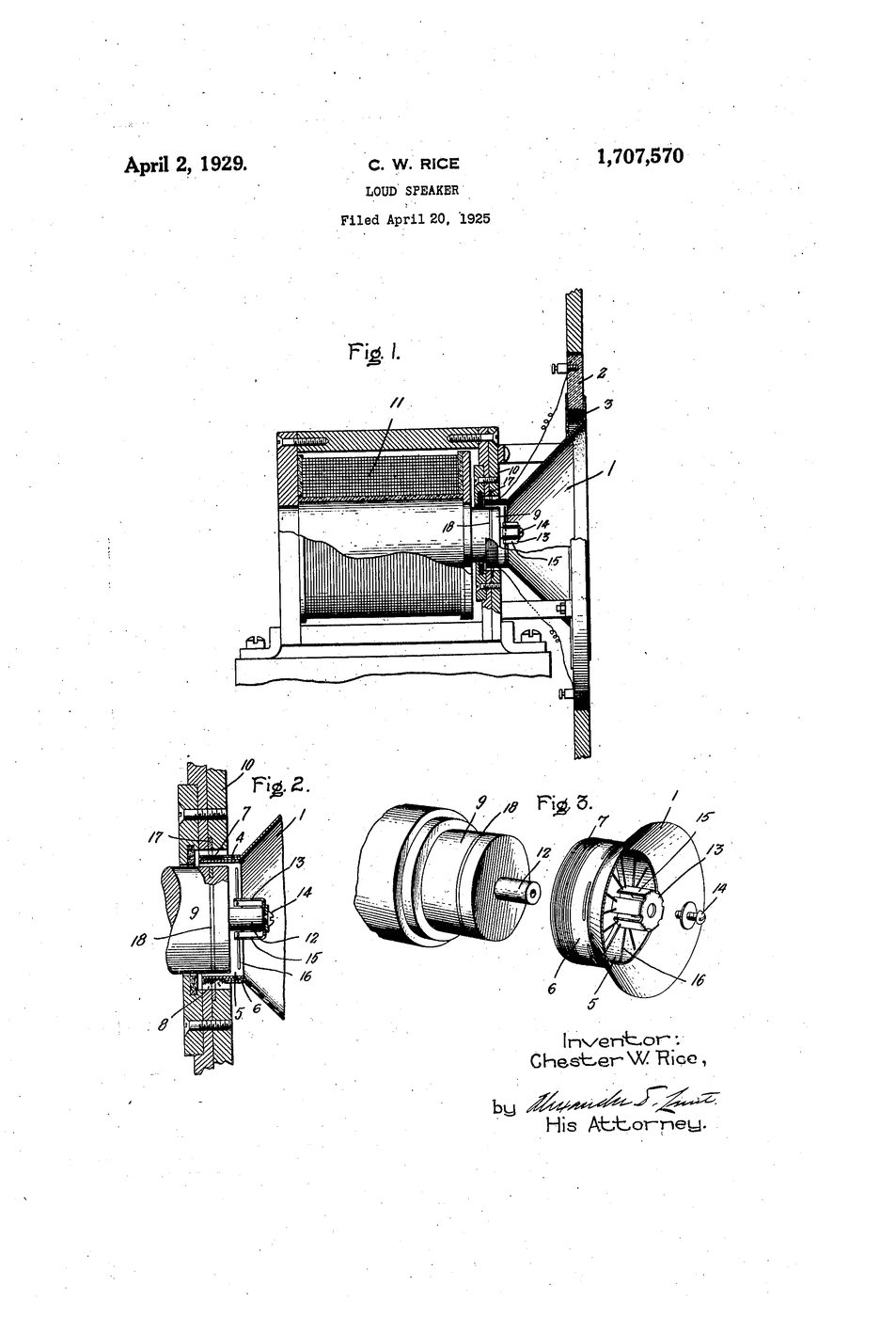
The moving-coil transducer is Chester Rice and Edward Kellogg's 1925 loudspeaker motor, already in this catalogue, used in reverse. Moving-coil microphones developed through the 1920s and 1930s at the same laboratories, and the dynamic microphone became the workhorse of broadcasting, public address and stage work — a position it still holds a century later.
Reciprocity is a deep property, not a coincidence. Any transducer that converts electrical energy to mechanical will convert mechanical to electrical, and the efficiency is the same in both directions. It applies to piezoelectric crystals, to electrostatic panels, to moving-iron elements. Once you know it, you can look at any actuator and ask what it would sense, and at any sensor and ask what it could drive.
Where this sits in the chain: the carbon microphone modulates an existing current and is noisy. The condenser needs power and an amplifier but is accurate. The moving coil generates its own signal from the sound's energy alone — no power, no amplifier at the capsule, nothing to go wrong. It is the most self-sufficient of the three.
Its honest limits: moving mass limits high-frequency response; output is low, so a good preamplifier still matters even though the capsule needs no power; and the magnet makes it heavy. Its ruggedness is precisely a consequence of that mass and mechanical simplicity, so the limitation and the virtue are the same property seen from two sides.
Materials
6- 1 pieceNOK 20.80
- 1 rollPlaceholder
- 1 piecePlaceholder
- 1 kitPlaceholder
- 1 metrePlaceholder
- 1 padPlaceholder
Tools Required
9- Placeholder
- Placeholder
- NOK 255.20
- Placeholder
- Placeholder
- Placeholder
- Placeholder
- Placeholder
Related Blueprints
These blueprints share knowledge with this one — techniques, materials, or principles that connect them in the learning graph.

CC0 Public Domain
This blueprint is released under CC0. You are free to copy, modify, distribute, and use this work for any purpose, without asking permission.
Support the Maker by purchasing products through their Blueprint where they earn a Maker Commission set by Vendors, or create a new iteration of this Blueprint and include it as a connection in your own Blueprint to share revenue.