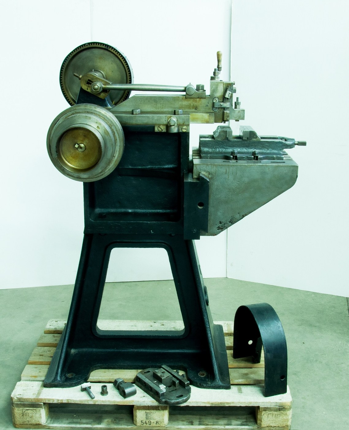


Shaping Machine
Mga Tagubilin
Build the column and the ram slideway
Build the column and the ram slideway
A vertical column carrying a horizontal ram — the whole machine in two parts.
- Build a column 300 mm tall from 18 mm ply, braced square with gussets.
- Fit two parallel aluminium angle ways along its top, 80 mm apart, for the ram.
- Fix with M5 × 30 socket head cap screws × 8, M5 flat washers × 16 and M5 hex nuts × 8.
- Check the ways are level and parallel with the combination square.
What the planer made possible. The ram ways need to be flat, straight and parallel — exactly the surfaces the planing machine was invented to produce. Nasmyth built shapers in a world where planers already existed to make their slideways, which is why the shaper arrives two decades after the planer rather than alongside it.
Brace the column properly. All the cutting force is transmitted from the ram down through this column into the base, and a column that flexes gives a surface that is flat in the middle and tapered at the ends.Mga materyales para sa hakbang na ito:
 Playwud na Baltic Birch1 pilyego
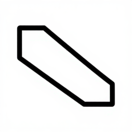 Kantonera ng aluminyo2 piraso
 Patag na Sinturon16 piraso
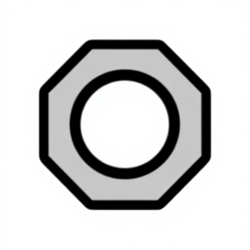 Tuerkang Heksagonal8 piraso
Mga kailangang kasangkapan:
 Lagaring Pangkurba
 Walang-Kableng Barena
 Hanay ng Talim ng Barena
 Hanay ng Susing Heks
 Panuka na Pinagsama
 Digital na Kalibrador 6 Pulgada
Fit the quick-return drive
Fit the quick-return drive
The mechanism from batch 68, now doing the job it was invented for.
- Mount a bull wheel of 160 mm diameter on the column side, on a 608 bearing.
- Set a second pivot 45 mm below its centre for the slotted link.
- Make the slotted link 260 mm long with a slot down its centre.
- Fit a crank pin on the bull wheel at 70 mm radius, carrying a 608 bearing that runs in the slot.
- Connect the link's top to the ram with a short connecting rod, using M5 × 25 socket head cap screws × 2, M5 flat washers × 4 and M5 hex nuts × 2.
Why this drive and not a plain crank. A shaper cuts on the forward stroke only. With a plain crank the return takes as long as the cut, so half the machine's time produces nothing. The offset slotted link makes the cutting stroke occupy more than half a revolution and the return less, raising output by a large fraction with no extra power. Whitworth built it into his machines in the 1840s and it became standard.
Set the offset before anything else and mark it on the frame, exactly as in the quick-return blueprint. Offset sets the time ratio; crank radius sets the stroke length; the two are independent.Mga materyales para sa hakbang na ito:
Playwud na Baltic Birch1 pilyego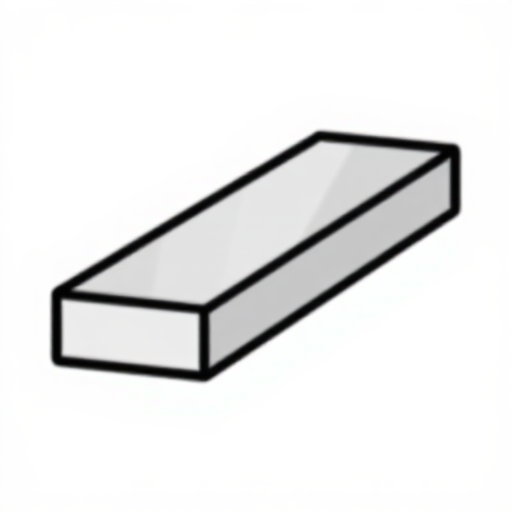 Patag na Bara ng Aluminyo1 piraso
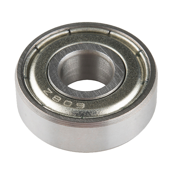 Ball Bearing - Non-Flanged (8mm Bore, 22mm OD)3 pirasoPatag na Sinturon8 pirasoTuerkang Heksagonal4 piraso
Mga kailangang kasangkapan:
 Lagaring PangkurbaWalang-Kableng BarenaHanay ng Talim ng Barena
 Hanay ng KikilHanay ng Susing HeksDigital na Kalibrador 6 Pulgada
 Pantudlok sa Gitna
Make the ram, clapper box and tool head
Make the ram, clapper box and tool head
Same clapper principle as the planer, now travelling instead of the work.
- Cut a ram 280 × 60 mm from 18 mm ply faced with aluminium, running on the column ways.
- Fit a vertical tool slide at its front end, adjustable up and down by an M6 screw.
- Hinge the tool holder to swing backward only, with a stop at vertical.
- Clamp an HSS tool blank in the holder with two M5 cup point set screws.
- Set the ram stroke by moving the crank pin, and set its position so the cut starts just before the work.
Stroke position matters as much as stroke length. Too far forward and the tool crashes into the vice; too far back and it wastes travel cutting air. Setting both is the standard shaper set-up procedure, and it is done for every job because the two adjustments are independent.
The clapper on a shaper is more important than on a planer, because the tool returns over the work at speed. A sticky clapper leaves a witness scratch on every return stroke, visible as a fine line across the finished surface.Mga materyales para sa hakbang na ito:
Playwud na Baltic Birch1 pilyegoPatag na Bara ng Aluminyo1 piraso Turnilyong pang-ipit na malukong ang dulo2 piraso
 Turnilyong May Ulong Soket2 piraso
 Tuwerkang Panghigpit na May Nylon2 piraso
Mga kailangang kasangkapan:
Lagaring PangkurbaWalang-Kableng BarenaHanay ng Talim ng BarenaHanay ng Susing HeksHanay ng KikilPanuka na PinagsamaAdd the pawl-and-ratchet table feed
Add the pawl-and-ratchet table feed
The table must step sideways once per stroke, automatically, at the right moment.
- Mount the work table on a cross slide driven by an M8 leadscrew.
- Fit a ratchet wheel to the leadscrew end.
- Drive a pawl from an eccentric on the bull wheel so it advances the ratchet one or more teeth per revolution.
- Arrange the linkage so the feed happens during the RETURN stroke.
- Change the feed rate by limiting how many teeth the pawl picks up.
Feeding on the return is essential. If the table steps sideways while the tool is cutting, the tool is loaded sideways and the surface shows a step. Feeding during the return means the work is always stationary during the cut. This is a genuine sequencing problem solved mechanically — the ratchet and pawl from batch 68, doing timing rather than just one-way holding.
Reverse the pawl to feed the other way, and note that the pawl's tooth pick-up is the feed adjustment. That is the same discrete-steps limitation the ratchet blueprint measured: you can have one tooth or two, not one and a half.Mga materyales para sa hakbang na ito:
Patag na Bara ng Aluminyo1 piraso Hanay ng Spring na Panipi1 setTurnilyong May Ulong Soket4 pirasoPatag na Sinturon8 pirasoTuwerkang Panghigpit na May Nylon4 piraso
Mga kailangang kasangkapan:
Lagaring PangkurbaHanay ng KikilWalang-Kableng BarenaHanay ng Talim ng BarenaHanay ng Susing HeksDigital na Kalibrador 6 PulgadaMeasure the time saved, and history
Measure the time saved, and history
Put a number on the quick-return, on the machine it was built for.
- Mark the bull wheel every 15 degrees.
- Record the crank angles at which the ram reverses at each end.
- Compute the cutting and return stroke times as a fraction of one revolution.
- Work out how many more strokes per hour that gives versus a symmetric drive.
History. James Nasmyth built his shaping machine around 1836, calling it a “steam arm” in his own account, and it spread rapidly because it did the planer's job for small work at a fraction of the cost and floor space. Nasmyth also gave this catalogue its steam hammer, three years later — the same instinct for building the machine the job actually needed.
Where it sits in the chain. The planer (1817) made flat surfaces possible by machine. The shaper (1836) made them affordable for small work. Together they gave the workshop accurate flat and square reference faces on ordinary parts — which is the precondition for the turret lathe and the milling machine that follow in this batch, because those machines' fixtures and beds are themselves flat surfaced work.
Why shapers largely disappeared: a milling cutter has many teeth cutting continuously, while a shaper has one tooth cutting half the time. Once milling machines and cheap cutters were available the shaper's productivity could not compete. They survive in small shops and toolrooms because they are simple, cheap, need no expensive cutters — a single ground HSS blank does everything — and will cut internal keyways and odd forms that a mill cannot reach.
Mga kailangang kasangkapan:
 Panukat ng OrasPanuka na Pinagsama
Mga Materyales
11- 1 pilyegoPlaceholder
- 2 pirasoPlaceholder
- 24 pirasoPlaceholder
- 12 pirasoPlaceholder
- 1 pirasoPlaceholder
- Ball Bearing - Non-Flanged (8mm Bore, 22mm OD)10% komisyon3 piraso$1.27
- Placeholder
- 6 pirasoPlaceholder
- Placeholder
- Placeholder
- 8 pirasoPlaceholder
Mga Kinakailangang Kasangkapan
10- 1 vendor sell this, none ship to you yetPlaceholder
- 1 vendor sell this, none ship to you yetPlaceholder
- Placeholder
- Placeholder
- Placeholder
- Placeholder
- Placeholder
- Placeholder
- Placeholder
- Placeholder
Kaugnay na Blueprint
Ang mga blueprint na ito ay nagbabahagi ng kaalaman — mga teknik, materyales, o prinsipyo

CC0 Pampublikong Domain
Ang blueprint na ito ay inilabas sa ilalim ng CC0. Malaya kang kumopya, magbago, mamahagi, at gumamit nang walang pahintulot.
Suportahan ang Maker sa pamamagitan ng pagbili ng mga produkto sa kanilang Blueprint Komisyon ng Maker itinakda ng mga Vendor, o lumikha ng bagong bersyon ng Blueprint na ito at isama bilang koneksyon sa iyong Blueprint upang ibahagi ang kita.