
Using a Shift Register — SIK Circuit 14
Mga Tagubilin
Parts & Introduction
Parts & Introduction
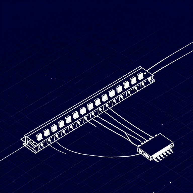
What if you need more outputs than the Arduino has pins? A shift register (74HC595) converts serial data into 8 parallel outputs — you send data on 3 pins and control 8 LEDs. You can chain multiple shift registers for even more outputs! This introduces SPI-style communication and bit manipulation.
Parts Needed
- 1x Arduino Uno + USB cable
- 1x Breadboard
- 1x 74HC595 Shift Register IC
- 8x LEDs (any color)
- 8x 330Ω Resistors
- 19x Jumper Wires
Mga materyales para sa hakbang na ito:
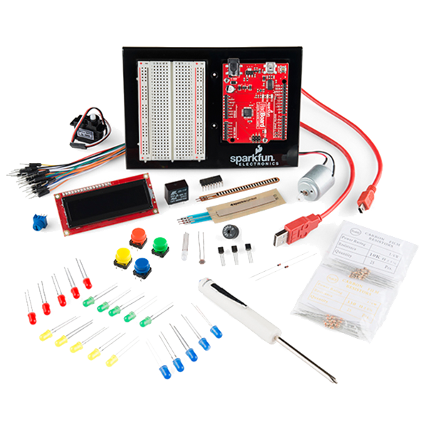 SparkFun Inventor's Kit - V3.21 kit
Mga kailangang kasangkapan:
 Kompyuter na May Arduino IDE
Hardware Hookup
Hardware Hookup
Wiring Instructions
Place the 74HC595 chip so it bridges the center canyon. The notch indicates pin 1.
74HC595 Pin Connections
| Pin | Name | Connection |
|---|---|---|
| 1 (QB) | Output B | LED 2 positive |
| 2 (QC) | Output C | LED 3 positive |
| 3 (QD) | Output D | LED 4 positive |
| 4 (QE) | Output E | LED 5 positive |
| 5 (QF) | Output F | LED 6 positive |
| 6 (QG) | Output G | LED 7 positive |
| 7 (QH) | Output H | LED 8 positive |
| 8 (GND) | Ground | GND |
| 10 (SRCLR*) | Clear | 5V (active low, keep high) |
| 11 (SRCLK) | Clock | Arduino Pin 3 |
| 12 (RCLK) | Latch | Arduino Pin 4 |
| 13 (OE*) | Output Enable | GND (active low) |
| 14 (SER) | Data | Arduino Pin 2 |
| 15 (QA) | Output A | LED 1 positive |
| 16 (VCC) | Power | 5V |
Connect each LED's negative leg through a 330Ω resistor to GND.
Mga materyales para sa hakbang na ito:
 Lapad na Pansubok1 piraso
 Mga Jumper Wire10 piraso
Arduino Code
Arduino Code
Open the Arduino IDE and upload the following sketch to your Arduino board.
Mga materyales para sa hakbang na ito:
 Arduino Uno R31 piraso
Mga kailangang kasangkapan:
Kompyuter na May Arduino IDETest & Experiment
Test & Experiment
What You Should See
The same LED patterns as Circuit 4 (chase, ping-pong, etc.) but using only 3 Arduino pins instead of 8! The shift register does the heavy lifting.
Troubleshooting
- Arduino power LED goes out: The chip is inserted backwards. Fix it quickly — no permanent damage if caught fast.
- Not working: With 19 wires, a crossed connection is likely. Double-check systematically.
Experiments to Try
- Uncomment
binaryCount()to see binary counting from 0-255 displayed on the LEDs. - Chain two 74HC595s together for 16 outputs from just 3 pins.
- Combine with a potentiometer to control the animation speed.
Mga Materyales
7- SparkFun Inventor's Kit - V3.210% komisyon1 kit$105.50
- Placeholder
- Placeholder
- Placeholder
- 1 pirasoPlaceholder
- Placeholder
- 8 pirasoPlaceholder
Mga Kinakailangang Kasangkapan
1- Placeholder
CC0 Pampublikong Domain
Ang blueprint na ito ay inilabas sa ilalim ng CC0. Malaya kang kumopya, magbago, mamahagi, at gumamit nang walang pahintulot.
Suportahan ang Maker sa pamamagitan ng pagbili ng mga produkto sa kanilang Blueprint Komisyon ng Maker itinakda ng mga Vendor, o lumikha ng bagong bersyon ng Blueprint na ito at isama bilang koneksyon sa iyong Blueprint upang ibahagi ang kita.