تعاون
فن
خوبصورتی اور تندرستی
دستکاری
ثقافت اور تاریخ
تفریح
ماحول
خوراک اور مشروبات
ریورس انجینئرنگ
سائنسز
کھیل
ٹیکنالوجی
پہننے والے آلات
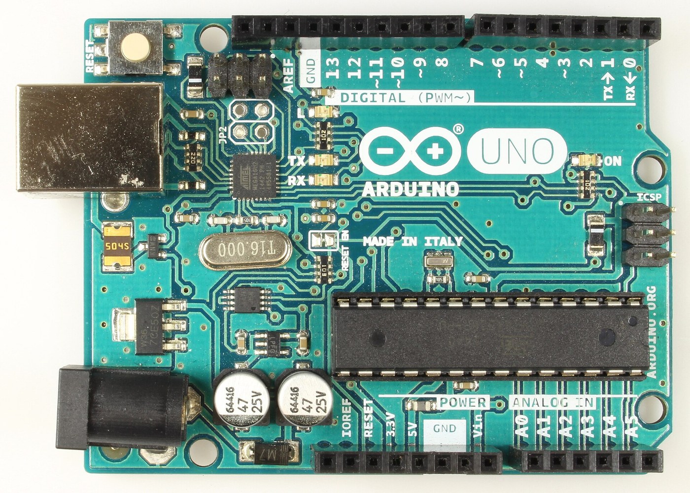


Arduino Uno R3: Assembled from Arduino's Open UNO-TH Rev3e Design Files and Flashed over ICSP
The Arduino Uno R3 is open hardware: Arduino publishes its schematic and board layout. This blueprint builds one from those files, part by part, then loads the firmware into its two processors.
Result: an Arduino Uno R3. An ATmega328P (16 MHz, 32 kB flash, 2 kB SRAM, 1 kB EEPROM) runs your programs; an ATmega16U2 turns USB into its serial link. It runs from USB (5.5 V at most) or 6-20 V at the DC jack.
Source: Arduino UNO-TH_Rev3e design files and the A000066 schematic and datasheet (Arduino, CC BY-SA). Unknown: how every bought part is made; no public source in hand says. The soldering method is ours. Picture: Wikimedia Commons.
اعلیٰ
1 day
ہدایات
1
1
Get the bare board
Get the bare board
Have the two-layer board made to Arduino's UNO-TH_Rev3e board layout (the .brd file of the design files). Check it against the schematic before fitting anything.
اس مرحلے کے لیے مواد:
 چھپا ہوا سرکٹ بورڈ1 UNO-TH Rev3e layout
درکار اوزار:
 مکبر لوپ
2
2
Fit the small surface-mount parts
Fit the small surface-mount parts
Solder the chip parts to their marked places: resistor arrays RN1 (10K), RN2 and RN4 (1K), RN3 (22R); R1, R2 (1M); capacitors C1, C2, C4-C7, C10 (100n), C3, C8 (1u), C9, C11 (22p); varistors Z1, Z2; ferrite bead L1; inductor L2 (10 uH); diodes D2, D3; LEDs ON (green), L, RX, TX (yellow). Ours: flux, tweezers and hot air or a fine iron, checked under a loupe.
اس مرحلے کے لیے مواد:
 چپ ریزسٹر اری4 RN1-RN4
 چپ ریزسٹر2 1M
 سرامک چپ کپیسٹر11 7x100n, 2x1u, 2x22p
 چپ ویریسٹر2 Z1, Z2
 فیرائٹ بیڈ1 L1
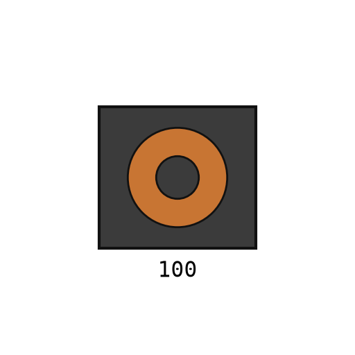 سطحی ماؤنٹ انڈکٹر1 L2
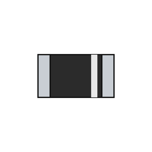 سطحی ماؤنٹ ڈائیوڈ2 D2, D3
 چپ LED4 1 green, 3 yellow
 ٹانکے کا تار1 a little
درکار اوزار:
 فلکس
 نوکیلی چمٹی
 گرم ہوا مرمت اسٹیشن
 ٹانکا لگانے کی سلاخمکبر لوپ
3
3
Fit the power and chip parts
Fit the power and chip parts
Solder the ATmega16U2 (U3), the 16 MHz resonator Y2 and crystal Y1, the 5 V regulator NCP1117 (U1) and 3.3 V regulator LP2985 (U2), the LMV358 op-amp (U5), the FDN340P transistor (T1), the M7 diode (D1), the 500 mA resettable fuse (F1) and the 47 uF capacitors PC1, PC2 with their polarity as marked.
اس مرحلے کے لیے مواد:
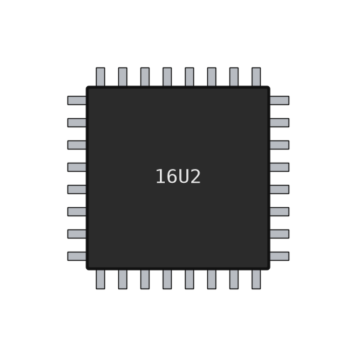 ATmega16U2 مائیکروکنٹرولر1 U3
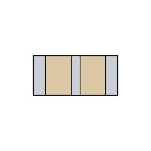 پیزوالیکٹرک سرامک ریزونیٹر1 Y2
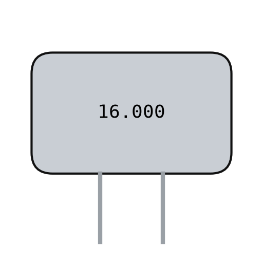 کوارٹز کرسٹل1 Y1
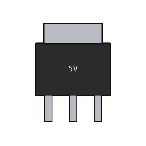 لکیری وولٹیج ریگولیٹر2 U1 5 V, U2 3.3 V
 آپ ایمپ آئی سی1 U5 LMV358
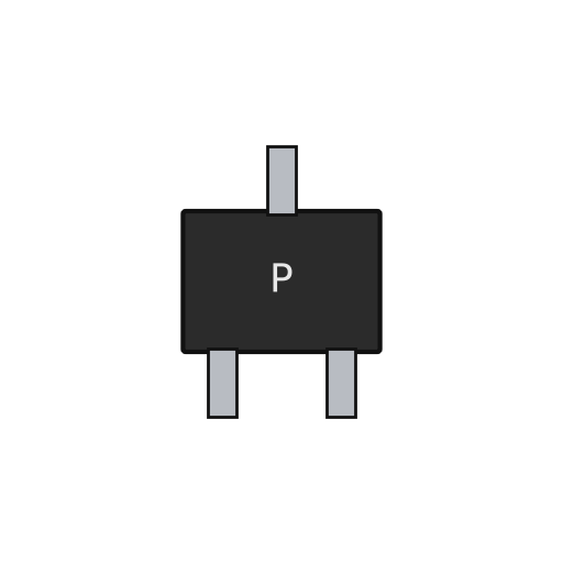 P چینل MOSFET1 T1سطحی ماؤنٹ ڈائیوڈ1 D1 M7
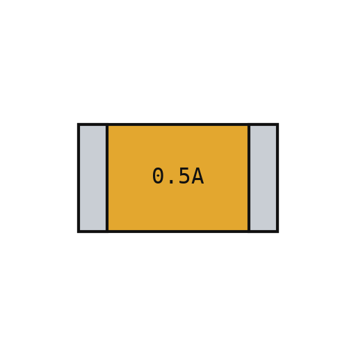 ری سیٹ ہونے والا فیوز1 F1
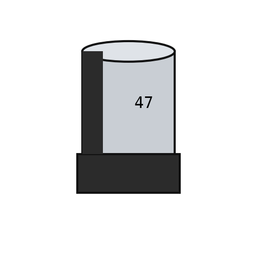 قطبی چپ کپیسٹر2 PC1, PC2ٹانکے کا تار1 a little
درکار اوزار:
فلکسنوکیلی چمٹیگرم ہوا مرمت اسٹیشنٹانکا لگانے کی سلاخمکبر لوپ4
4
Fit the through-hole parts
Fit the through-hole parts
Solder the USB-B socket (X2), the DC jack (X1), the reset switch, the female headers (one 10-way, two 8-way, one 6-way) and the two 2x3 ICSP headers. Seat the ATmega328P in its place (ZU4).
اس مرحلے کے لیے مواد:
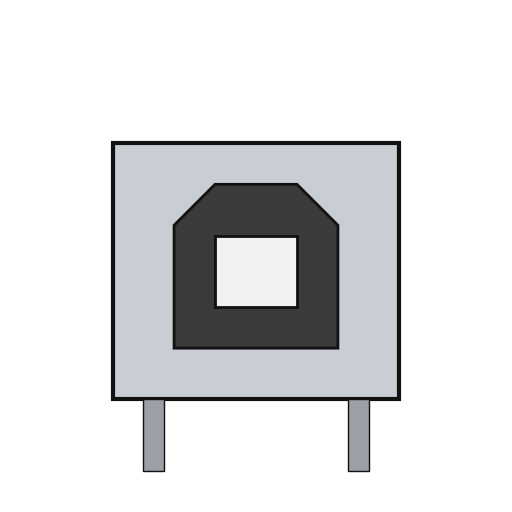 USB-B ساکٹ1 X2
 بیرل پاور ساکٹ1 X1
 دبانے کا بٹن1 RESET
 پن ہیڈر6 10x1, 2x 8x1, 6x1 female; 2x 3x2 ICSP
 ATmega328P مائیکروکنٹرولر1 ZU4ٹانکے کا تار1 as needed
درکار اوزار:
ٹانکا لگانے کی سلاخ5
5
Flash and check
Flash and check
Check with a meter that 5 V and GND are not shorted. Through the ICSP headers, load the USB-to-serial firmware into the ATmega16U2 and the bootloader into the ATmega328P. Plug in USB: the green ON LED lights, and the blink test in the next step flashes the L LED. Ours: an AVR ISP programmer and a multimeter.
اس مرحلے کے لیے مواد:
 Arduino Uno فرم ویئر1 download
درکار اوزار:
 ملٹی میٹر
 AVR ISP پروگرامر
 USB-B کیبل
6
6
The blink test
The blink test
blink_test.ino: the same check as Arduino's Blink example. Upload it over USB from the Arduino IDE with the board set to Arduino Uno; the L LED on pin 13 turns on for one second and off for one second, over and over. If it does, both processors, the USB link and the bootloader work.
blink_test.inocpp
درکار اوزار:
USB-B کیبلمواد
24- 1 UNO-TH Rev3e layoutپلیس ہولڈر
- 4 RN1-RN4پلیس ہولڈر
- 2 1Mپلیس ہولڈر
- 11 7x100n, 2x1u, 2x22pپلیس ہولڈر
- 2 Z1, Z2پلیس ہولڈر
- 1 L1پلیس ہولڈر
- پلیس ہولڈر
- 1 D1 M7پلیس ہولڈر
- 4 1 green, 3 yellowپلیس ہولڈر
- 1 as neededپلیس ہولڈر
- پلیس ہولڈر
- پلیس ہولڈر
- 1 Y1پلیس ہولڈر
- 2 U1 5 V, U2 3.3 Vپلیس ہولڈر
- 1 U5 LMV358پلیس ہولڈر
- 1 T1پلیس ہولڈر
- پلیس ہولڈر
- 2 PC1, PC2پلیس ہولڈر
- 1 X2پلیس ہولڈر
- پلیس ہولڈر
- پلیس ہولڈر
- پلیس ہولڈر
- پلیس ہولڈر
- 1 downloadپلیس ہولڈر
درکار اوزار
8- پلیس ہولڈر
- پلیس ہولڈر
- پلیس ہولڈر
- پلیس ہولڈر
- 2 vendors sell this, none ship to you yetپلیس ہولڈر
- پلیس ہولڈر
- پلیس ہولڈر
- 1 vendor sell this, none ship to you yetپلیس ہولڈر
یہ بلوپرنٹ بناتا ہے
متعلقہ بلیو پرنٹ
یہ بلیو پرنٹ علم بانٹتے ہیں — تکنیک، مواد یا اصول
CC0 پبلک ڈومین
یہ بلیو پرنٹ CC0 کے تحت جاری کیا گیا ہے۔ آپ اجازت لیے بغیر اس کام کو نقل، ترمیم، تقسیم اور کسی بھی مقصد کے لیے استعمال کرنے کے لیے آزاد ہیں۔
میکر کی حمایت کریں ان کے بلیو پرنٹ کے ذریعے پروڈکٹس خرید کر جہاں وہ میکر کمیشن وینڈرز کی طرف سے مقرر، کماتے ہیں، یا اس بلیو پرنٹ کی نئی تکرار بنائیں اور آمدنی شیئر کرنے کے لیے اسے اپنے بلیو پرنٹ میں کنکشن کے طور پر شامل کریں۔