تعاون
فن
خوبصورتی اور تندرستی
دستکاری
ثقافت اور تاریخ
تفریح
ماحول
خوراک اور مشروبات
ریورس انجینئرنگ
سائنسز
کھیل
ٹیکنالوجی
پہننے والے آلات
چپ پر SRAM: ایک سانس لیتی روشنی جو آپ کی چپ کی اپنی میموری میں محفوظ ہے
English
Youblob (simulation output) · CC0

Ed

تخلیق کار

Ed

29. ستمبر 2026FI
51
0
0
0
0

چپ پر SRAM: ایک سانس لیتی روشنی جو آپ کی چپ کی اپنی میموری میں محفوظ ہے

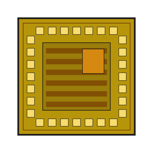
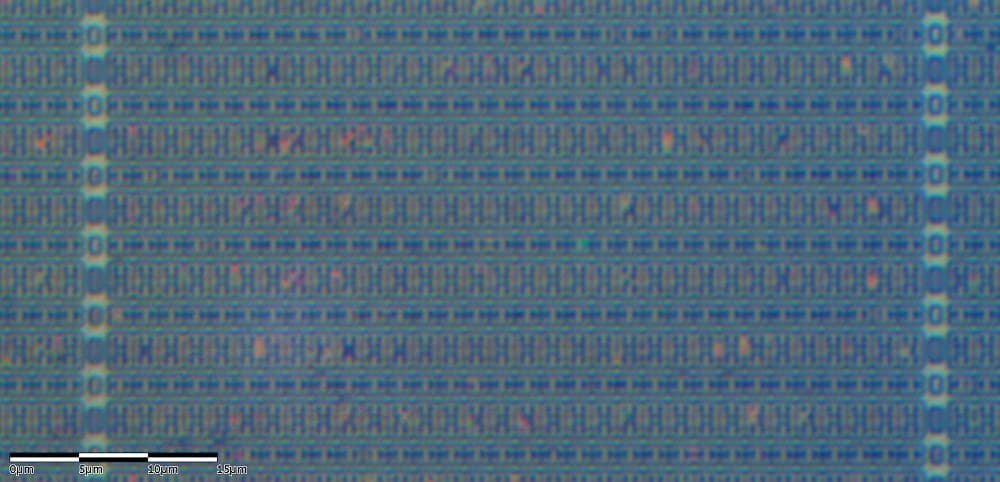
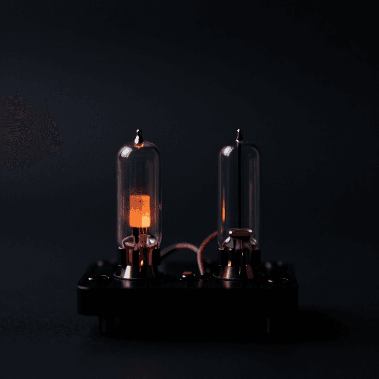
wafer.space کے ٹیمپلیٹ میں اس کے مثالی ڈیزائن میں دو SRAM میکرو شامل ہیں، ہر ایک 512 بائٹس کا، اور انہیں بند چھوڑا گیا ہے۔ میکرو PDK کا ایک مکمل میموری بلاک ہے: 4,096 جامد میموری سیلز، جنہیں ان کے ایڈریس ڈی کوڈر اور ریڈ سرکٹس کے ساتھ ایک بار ڈرا کیا گیا ہے، اور آپ انہیں گیٹس سے بنانے کے بجائے پورا رکھتے ہیں۔ یہ مرحلہ ایک کو آن کرتا ہے۔ پچھلے مرحلے کا PWM ڈمر اب ایک پیٹرن چلاتا ہے: ایک مائیکروکنٹرولر اپنے پیڈز کے ذریعے چپ میں 256 بائٹس ایک بار لکھتا ہے، اور اس کے بعد چپ انہیں خود سے ایک ایک قدم میں پڑھتی ہے، بطور آہستہ سانس لیتی روشنی کی چمک۔ کور اور اس کے ٹیسٹ بنچ کو اس بلیو پرنٹ کے لیے Icarus Verilog 12.0، cocotb 2.1.0 اور PDK کے اپنے سمولیشن ماڈل کے SRAM میکرو کے ساتھ چلایا گیا: آؤٹ پٹ 600 PWM پیریڈز تک محفوظ کردہ ٹیبل کی پیروی کرتا رہا۔ تصویر اس سمولیشن کا اپنا آؤٹ پٹ ہے، ہر پیریڈ کے لیے ایک بار۔ وہ ESP32 اسکیچ جو ٹیبل لوڈ کرتا ہے اس بلیو پرنٹ کے لیے کمپائل کیا گیا تھا؛ ابھی تک کوئی چپ نہیں ہے جس پر اسے چلایا جا سکے۔
اعلیٰ
ایک شام، اور چپ

ہدایات

1

پیٹرن، وقت اور سائز

Jupyter نوٹ بک لوڈ ہو رہی ہے…
2

ان 4,096 بٹس میں سے ہر ایک کیا ہے

ایمبیڈڈ بلیو پرنٹ دکھاتا ہے کہ اسٹیٹک میموری کا ایک بٹ خود کو کیسے تھامے رکھتا ہے: دو انورٹرز کا ایک لوپ۔ اس رنگ میں میکرو ایک ہی ارے میں 4,096 بٹس اسٹیٹک میموری ہے۔
3

میکرو کے پن، اور اس کا ماڈل بیان کرنے والی تین باتیں

gf180mcu_fd_ip_sram__sram512x8m8wm1 میں 512 بائٹس ہیں۔ اس کے پن: CLK; A، ایک 9-بٹ ایڈریس؛ D، وہ بائٹ جو لکھنی ہے؛ Q، وہ بائٹ جو پڑھی گئی۔ تینوں کنٹرول سب کے سب LOW فعال ہیں۔ CEN کو 0 پر رکھنے سے میموری آن ہو جاتی ہے۔ GWEN کو 0 پر رکھنے سے کلاک ایج لکھنے کا عمل بنتی ہے، 1 پر پڑھنے کا۔ WEN ڈیٹا بٹ کے حساب سے ایک بٹ ہے، اور 0 اس بٹ کو لکھنے دیتا ہے، لہذا ایک لکھنے کے عمل سے بائٹ کے کچھ بٹس بدل سکتے ہیں اور باقی چھوڑے جا سکتے ہیں۔ PDK کے سمیولیشن ماڈل کو پڑھنے سے تین باتیں معلوم ہوتی ہیں۔ پہلی، میموری تبھی کام کرتی ہے جب CEN 1 سے 0 پر آ جائے؛ ورنہ ماڈل "CEN ری سیٹ نہیں ہے، میموری آپریشنل نہیں ہے" پرنٹ کرتا ہے، لہذا کور ری سیٹ کے دوران CEN کو 1 پر رکھتا ہے اور اس کے بعد نیچے کرتا ہے۔ دوسری، پڑھنے کا عمل کلاک ایج کے فوراً بعد Q پر mem[A] دیتا ہے جس نے A کو سیمپل کیا، لہذا ڈیٹا ایک کلاک بعد تیار ہوتا ہے۔ تیسری، ماڈل ہر بائٹ کو 0 سے شروع کرتا ہے۔ حقیقی چپ ایسا نہیں کرتی: اس کا SRAM اسی حالت میں آن ہوتا ہے جس میں ہر سیل گرا تھا، لہذا ڈیزائن کو پڑھنے سے پہلے لکھنا ہوگا۔ ٹیمپلیٹ کی اپنی مثال CEN کو 1 سے جوڑتی ہے، لہذا اس کے دونوں میکرو بند رہتے ہیں۔ اس کی ٹائمنگ فائلیں میکرو کی کم از کم کلاک پیریڈ عام 5 V کارنر پر 6.6 ns اور سست 3.0 V، 125 °C کارنر پر 18.3 ns بتاتی ہیں، دونوں ٹیمپلیٹ کے 40 ns کے اندر اچھی طرح ہیں۔
4

The core

src/chip_core.sv for the pattern player, with the template's port list unchanged plus one parameter, HOLD_LOG2. Input pad 0 enables, pad 1 selects LOAD mode, pad 2 is the write strobe; bidirectional pads 0 to 7 carry the byte, pad 8 the PWM. The LOAD and strobe pads are passed through two flip-flops before use, a synchroniser: they change whenever the outside world likes, not in step with the chip's clock, and a flip-flop caught mid-change can hover between 0 and 1 for a while. In play mode, each time HOLD_LOG2 periods have passed, the byte the SRAM has been reading becomes the new duty and the address moves on.
chip_core.svsystemverilog
// SPDX-License-Identifier: Apache-2.0
// Youblob silicon rung 5: the PWM dimmer plays a brightness pattern stored in the on-chip SRAM macro.
// Port list unchanged from wafer-space/gf180mcu-project-template src/chip_core.sv.

`default_nettype none

module chip_core #(
    parameter NUM_INPUT_PADS,
    parameter NUM_BIDIR_PADS,
    parameter NUM_ANALOG_PADS,
    parameter HOLD_LOG2 = 9        // each table entry lasts 2**HOLD_LOG2 PWM periods
    )(
    `ifdef USE_POWER_PINS
    inout  wire VDD,
    inout  wire VSS,
    `endif

    input  wire clk,       // clock
    input  wire rst_n,     // reset (active low)

    input  wire [NUM_INPUT_PADS-1:0] input_in,   // Input value
    output wire [NUM_INPUT_PADS-1:0] input_pu,   // Pull-up
    output wire [NUM_INPUT_PADS-1:0] input_pd,   // Pull-down

    input  wire [NUM_BIDIR_PADS-1:0] bidir_in,   // Input value
    output wire [NUM_BIDIR_PADS-1:0] bidir_out,  // Output value
    output wire [NUM_BIDIR_PADS-1:0] bidir_oe,   // Output enable
    output wire [NUM_BIDIR_PADS-1:0] bidir_cs,   // Input type (0=CMOS Buffer, 1=Schmitt Trigger)
    output wire [NUM_BIDIR_PADS-1:0] bidir_sl,   // Slew rate (0=fast, 1=slow)
    output wire [NUM_BIDIR_PADS-1:0] bidir_ie,   // Input enable
    output wire [NUM_BIDIR_PADS-1:0] bidir_pu,   // Pull-up
    output wire [NUM_BIDIR_PADS-1:0] bidir_pd,   // Pull-down

    inout  wire [NUM_ANALOG_PADS-1:0] analog  // Analog
);

    // Input pad 0: enable.  Input pad 1: LOAD mode.  Input pad 2: write strobe.
    // Bidir pads 0..7: the byte to store while loading.  Bidir pad 8: the PWM output.
    localparam DUTY_W = 8;
    localparam PWM_PAD = 8;

    assign input_pu = '0;
    assign input_pd = '0;
    assign bidir_oe = {{(NUM_BIDIR_PADS-DUTY_W){1'b1}}, {DUTY_W{1'b0}}};
    assign bidir_ie = ~bidir_oe;
    assign bidir_cs = {{(NUM_BIDIR_PADS-DUTY_W){1'b0}}, {DUTY_W{1'b1}}};
    assign bidir_sl = '0;
    assign bidir_pu = '0;
    assign bidir_pd = '0;

    wire enable = input_in[0];
    wire [DUTY_W-1:0] data_in = bidir_in[DUTY_W-1:0];

    // The mode and strobe pads change whenever the outside world likes, not in step with clk:
    // two flip-flops in a row (a synchroniser) before anything uses them.
    logic [1:0] load_s;
    logic [2:0] strobe_s;
    always_ff @(posedge clk) begin
        load_s   <= {load_s[0], input_in[1]};
        strobe_s <= {strobe_s[1:0], input_in[2]};
    end
    logic load_was;
    wire load        = load_s[1];
    wire load_start  = load & ~load_was;
    wire strobe_rise = strobe_s[1] & ~strobe_s[2];
    always_ff @(posedge clk) load_was <= load;

    // The SRAM wants its chip enable (CEN, active LOW) to go 1 -> 0 before it works:
    // hold it at 1 through reset, then 0.
    logic cen;
    always_ff @(posedge clk) cen <= !rst_n;

    // PWM counter and the "hold" counter that decides when to step to the next table entry.
    logic [DUTY_W-1:0] count;
    logic [HOLD_LOG2:0] hold;                   // one bit wider so HOLD_LOG2 = 0 still works
    wire period_end = (count == '1);
    localparam logic [HOLD_LOG2:0] HOLD_MASK = (1 << HOLD_LOG2) - 1;   // 0 when HOLD_LOG2 = 0
    wire step = period_end && ((hold & HOLD_MASK) == HOLD_MASK);

    logic [DUTY_W-1:0] addr;
    logic [DUTY_W-1:0] duty;
    wire  [DUTY_W-1:0] q;                       // SRAM read data: mem[addr], one clock after addr

    always_ff @(posedge clk) begin
        if (!rst_n) begin
            count <= '0;  hold <= '0;  addr <= '0;  duty <= '0;
        end else if (load) begin
            count <= '0;  hold <= '0;  duty <= '0;
            if (load_start)       addr <= '0;       // every load starts at entry 0
            else if (strobe_rise) addr <= addr + 1'b1;
        end else if (enable) begin
            count <= count + 1'b1;
            if (period_end) hold <= hold + 1'b1;
            if (step) begin
                duty <= q;                          // the entry that was being read
                addr <= addr + 1'b1;                // and move on to the next
            end
        end
    end

    `gf180mcu_xxx_ip_sram__sram512x8m8wm1 sram_0 (
        `ifdef USE_POWER_PINS
        .VDD  (VDD),
        .VSS  (VSS),
        `endif
        .CLK  (clk),
        .CEN  (cen),                                   // active low: 0 = on
        .GWEN (~(load && strobe_rise)),                // active low: 0 = write this clock
        .WEN  (8'b0),                                  // active low, per bit: write all eight
        .A    ({1'b0, addr}),                          // 256 of the 512 bytes
        .D    (data_in),
        .Q    (q)
    );

    logic pwm;
    always_ff @(posedge clk) begin
        if (!rst_n) pwm <= 1'b0;
        else        pwm <= enable && !load && (count < duty);
    end

    logic [NUM_BIDIR_PADS-1:0] out;
    always_comb begin
        out = '0;
        out[PWM_PAD] = pwm;
    end
    assign bidir_out = out;

    // Inputs this design does not read (keeps lint quiet, as the template does with _unused).
    logic _unused;
    assign _unused = &{1'b0, input_in[NUM_INPUT_PADS-1:3], bidir_in[NUM_BIDIR_PADS-1:DUTY_W], hold[HOLD_LOG2]};

endmodule

`default_nettype wire

درکار اوزار:

ڈیسک ٹاپ کمپیوٹرڈیسک ٹاپ کمپیوٹر
5

The test

test_pattern.py builds the core with the PDK's SRAM model, gf180mcu_fd_ip_sram__sram512x8m8wm1.v, at the template's 25 MHz and with HOLD_LOG2 = 0 so the whole table plays in 256 periods. It loads the table through the pads the way the ESP32 will, then counts the high clocks in each of 600 PWM periods and requires them to follow the table from exactly one starting point. A second test loads again and checks the new pattern replaced the old.
test_pattern.pypython
# SPDX-License-Identifier: Apache-2.0
# cocotb testbench for the SRAM pattern player, with the PDK's own SRAM simulation model
# (gf180mcu_fd_ip_sram__sram512x8m8wm1, gf180mcuD, the commit the template pins).
import math
import os
from pathlib import Path

import cocotb
from cocotb.clock import Clock
from cocotb.triggers import ClockCycles, FallingEdge, RisingEdge
from cocotb_tools.runner import get_runner

PWM_PAD = 8
EN, LOAD, STROBE = 1, 2, 4                      # input pad bits
SRAM = Path(os.getenv("PDK_ROOT", "pdk")) / "gf180mcuD" / "libs.ref" / "gf180mcu_fd_ip_sram" / "verilog"


def breathing_table(n=256, gamma=2.2):
    """One slow breath: a raised sine, gamma-corrected so equal steps LOOK equal to the eye."""
    return [round(255 * ((1 - math.cos(2 * math.pi * i / n)) / 2) ** gamma) for i in range(n)]


async def start(dut):
    cocotb.start_soon(Clock(dut.clk, 40, unit="ns").start())   # 25 MHz, the template's CLOCK_PERIOD
    dut.input_in.value = 0
    dut.bidir_in.value = 0
    dut.rst_n.value = 0
    await ClockCycles(dut.clk, 5)
    dut.rst_n.value = 1
    await ClockCycles(dut.clk, 2)


async def load(dut, table):
    """What a microcontroller on the breakout does: LOAD high, then per byte set the data pads,
    raise the strobe, wait, lower it. The chip synchronises the strobe, so hold each for 4 clocks."""
    dut.input_in.value = LOAD
    await ClockCycles(dut.clk, 4)
    for b in table:
        dut.bidir_in.value = b
        await ClockCycles(dut.clk, 1)
        dut.input_in.value = LOAD | STROBE
        await ClockCycles(dut.clk, 4)
        dut.input_in.value = LOAD
        await ClockCycles(dut.clk, 4)
    dut.input_in.value = 0
    await ClockCycles(dut.clk, 4)


async def highs_per_period(dut, periods):
    """High clocks in each PWM period, counted from the core's own count = 0."""
    while int(dut.count.value) != 0:
        await RisingEdge(dut.clk)
    out = []
    for _ in range(periods):
        n = 0
        for _ in range(256):
            await FallingEdge(dut.clk)
            n += int(dut.bidir_out.value[PWM_PAD])
        out.append(n)
    return out


@cocotb.test()
async def test_plays_the_table(dut):
    """Load a 256-entry breathing table, play it: each period's high time is the next entry."""
    table = breathing_table()
    await start(dut)
    await load(dut, table)
    dut.input_in.value = EN
    got = await highs_per_period(dut, 600)
    # the output starts part-way through the table; find where, then demand every period match
    fits = [off for off in range(256) if all(got[j] == table[(j + off) % 256] for j in range(2, 600))]
    dut._log.info(f"first periods {got[:8]}, table aligns at offset {fits}")
    Path(__file__).resolve().parent.joinpath("pattern_trace.csv").write_text("\n".join(map(str, got)))
    assert len(fits) == 1, f"the output does not follow the table (offsets that fit: {fits})"


@cocotb.test()
async def test_reload(dut):
    """Loading again replaces the pattern: a flat 64 gives 64 high clocks every period."""
    await start(dut)
    await load(dut, breathing_table())
    await load(dut, [64] * 256)
    dut.input_in.value = EN
    got = await highs_per_period(dut, 40)
    assert all(g == 64 for g in got[2:]), got


def test_runner():
    here = Path(__file__).resolve().parent
    defines = {"gf180mcu_xxx_ip_sram__sram512x8m8wm1": "gf180mcu_fd_ip_sram__sram512x8m8wm1"}
    runner = get_runner("icarus")
    runner.build(
        sources=[SRAM / "gf180mcu_fd_ip_sram__sram512x8m8wm1.v", here / "chip_core.sv"],
        hdl_toplevel="chip_core",
        parameters={"NUM_INPUT_PADS": 4, "NUM_BIDIR_PADS": 38, "NUM_ANALOG_PADS": 4, "HOLD_LOG2": 0},
        defines=defines,
        build_args=["-g2012"],
        timescale=("1ns", "1ps"),
        always=True,
    )
    runner.test(hdl_toplevel="chip_core", test_module="test_pattern")


if __name__ == "__main__":
    test_runner()

درکار اوزار:

ڈیسک ٹاپ کمپیوٹرڈیسک ٹاپ کمپیوٹر
6

سمولیشن نے کیا پرنٹ کیا

اس بلیو پرنٹ کے لیے Icarus Verilog 12.0 اور cocotb 2.1.0 کے ساتھ چلایا گیا: -------- MESSAGE: CEN abhi reset hua hai, memory operational hai --------- test_pattern.test_plays_the_table PASS (600 periods، table ایک ہی offset پر align ہوتا ہے) test_pattern.test_reload PASS TESTS=2 PASS=2 FAIL=0 SKIP=0 یہ ثابت کرنے کے لیے کہ ٹیسٹ ناکام ہو سکتا ہے، WEN کو 8'b0 سے 8'hFF میں تبدیل کیا گیا، یہ active-low pin کے ساتھ کلاسک غلطی ہے: ہر bit masked، کچھ بھی نہیں لکھا گیا، اور صفروں کا ایک table۔ دونوں ٹیسٹ ناکام ہوئے، اور core کو واپس رکھ دیا گیا۔ پہلی لائن SRAM model کا اپنا پیغام ہے: reset کے بعد core نے CEN کو نیچے کیا، جیسا کہ model تقاضا کرتا ہے۔
7

Load it from an ESP32

Once the chip is on its breakout board, this sketch writes the table. Eight GPIOs carry the byte, three more drive LOAD, the strobe and enable, and an LED with a 330 ohm resistor from pad 8 to ground shows the breath. Each level is held for 1 microsecond, 25 of the chip's clocks, so the synchroniser always sees it. The sketch then does nothing: the pattern lives in the chip. It is lost when the chip loses power, so send r over serial to load it again. The ESP32 is a 3.3 V part and its inputs are not 5 V tolerant. The sketch only drives the chip and never reads from it. The template's default libraries are the 5 V ones; before you connect, check in the I/O library's documentation that 3.3 V is a valid logic high for your chip's inputs, or build with the 3.3 V libraries, as the template's README shows. The sketch compiles for the ESP32 with the Arduino ESP32 core 3.3.12; it has not been run, because the chip does not exist yet.
load_pattern.inocpp
// SPDX-License-Identifier: Apache-2.0
// Load a breathing pattern into your chip's SRAM through its pads, then let the chip play it.
// Youblob silicon rung 5. The chip does the playing; this board only writes 256 bytes once.
//
// Wiring (ESP32 GPIO -> chip pad on your breakout):
//   D0..D7  GPIO 13,14,18,19,21,22,23,25 -> bidir[0..7]
//   LOAD    GPIO 26 -> input[1]
//   STROBE  GPIO 27 -> input[2]
//   EN      GPIO 32 -> input[0]
//   and a common ground. The chip's bidir[8] drives an LED through 330 ohm to ground.
// The ESP32 is a 3.3 V part: run the chip's I/O at 3.3 V, or put a level shifter between them.

#include <math.h>

const int DATA_PINS[8] = {13, 14, 18, 19, 21, 22, 23, 25};
const int PIN_LOAD = 26, PIN_STROBE = 27, PIN_EN = 32;

// The chip passes LOAD and STROBE through a two-flip-flop synchroniser and looks for the strobe's
// rising edge, so every level has to last a few of ITS clocks. 1 us is 25 clocks at 25 MHz.
const unsigned HOLD_US = 1;

uint8_t table[256];

void makeBreathingTable() {
  // a raised sine, gamma-corrected (2.2) so the brightness steps look even to the eye
  for (int i = 0; i < 256; i++) {
    float s = (1.0f - cosf(2.0f * PI * i / 256.0f)) / 2.0f;
    table[i] = (uint8_t)lroundf(255.0f * powf(s, 2.2f));
  }
}

void putByte(uint8_t b) {
  for (int bit = 0; bit < 8; bit++) digitalWrite(DATA_PINS[bit], (b >> bit) & 1);
  delayMicroseconds(HOLD_US);            // data settles before the strobe
  digitalWrite(PIN_STROBE, HIGH);        // the chip writes on the strobe's rising edge...
  delayMicroseconds(HOLD_US);            // ...a few of its clocks later, so hold the data
  digitalWrite(PIN_STROBE, LOW);
  delayMicroseconds(HOLD_US);
}

void loadTable() {
  digitalWrite(PIN_EN, LOW);
  digitalWrite(PIN_LOAD, HIGH);          // entering LOAD resets the chip's address to 0
  delayMicroseconds(HOLD_US);
  for (int i = 0; i < 256; i++) putByte(table[i]);
  digitalWrite(PIN_LOAD, LOW);
  delayMicroseconds(HOLD_US);
}

void setup() {
  Serial.begin(115200);
  for (int bit = 0; bit < 8; bit++) pinMode(DATA_PINS[bit], OUTPUT);
  pinMode(PIN_LOAD, OUTPUT);
  pinMode(PIN_STROBE, OUTPUT);
  pinMode(PIN_EN, OUTPUT);
  digitalWrite(PIN_STROBE, LOW);

  makeBreathingTable();
  loadTable();
  digitalWrite(PIN_EN, HIGH);            // play
  Serial.println("pattern loaded; the chip is playing it on its own");
  Serial.printf("table[0]=%u table[64]=%u table[128]=%u\n", table[0], table[64], table[128]);
}

void loop() {
  // Nothing to do: the pattern lives in the chip's SRAM now.
  // Send 'r' over serial to load it again (the SRAM loses it when the chip loses power).
  if (Serial.available() && Serial.read() == 'r') {
    loadTable();
    digitalWrite(PIN_EN, HIGH);
    Serial.println("reloaded");
  }
}

اس مرحلے کے لیے مواد:

کسٹم ASIC ڈائیکسٹم ASIC ڈائی1 ٹکڑا
چھپا ہوا سرکٹ بورڈچھپا ہوا سرکٹ بورڈ1 ٹکڑا
۵ ملی میٹر ایل ای ڈی۵ ملی میٹر ایل ای ڈی1 ٹکڑا
۳۳۰ اوہم مزاحم۳۳۰ اوہم مزاحم1 ٹکڑا

درکار اوزار:

ESP32 ترقیاتی بورڈESP32 ترقیاتی بورڈ
بریڈ بورڈبریڈ بورڈ
جمپر تاریںجمپر تاریں
ڈیسک ٹاپ کمپیوٹرڈیسک ٹاپ کمپیوٹر
8

ایک ایسا پیٹرن جو محفوظ نہیں ہوتا یا نہیں چلتا

SRAM پیٹرن کی خرابی کا سراغ لگانا۔

Flow

Loading...
9

ماخذ اور دیانتدارانہ حدود

**ماخذ**، 29 ستمبر 2026 کو پڑھے گئے: GF180MCU PDK اُس کمٹ پر جو ٹیمپلیٹ پن کرتا ہے (gf180mcuD، f6eeac7dad085ffcc829ccfd721f7b4ce39edcf7، fossi-foundation ciel releases سے؛ Apache-2.0): SRAM ماڈل gf180mcu_fd_ip_sram__sram512x8m8wm1.v، اس کا LEF بیرونی خاکے کے لیے، اور اس کی ٹائمنگ فائلیں کم از کم کلاک پیریڈ کے لیے؛ معیاری سیل لائبریری کی ٹائمنگ فائل فلپ فلاپ کے رقبے کے لیے۔ wafer-space/gf180mcu-project-template ریپوزیٹری (src/chip_core.sv، src/chip_top.sv، README.md، librelane/config.yaml؛ Apache-2.0)۔ **دیانتدارانہ حدود۔** سمولیشن chip_core کی سطح پر ہے، SRAM کے اپنے ماڈل کے ساتھ، مگر pad ring، synthesis یا layout کے بغیر، اور ماڈل کی ٹائمنگ چیکس یہاں کچھ طے نہیں کرتیں۔ ESP32 اسکیچ کمپائل ہوا، چلایا نہیں گیا۔ HOLD_LOG2 ٹیسٹ میں 0 رکھا گیا تاکہ وہ ختم ہو جائے؛ چپ 9 استعمال کرتی، تقریباً 1.3 سیکنڈ کا ایک وقفہ۔

مواد

4

درکار اوزار

4

CC0 پبلک ڈومین

یہ بلیو پرنٹ CC0 کے تحت جاری کیا گیا ہے۔ آپ اجازت لیے بغیر اس کام کو نقل، ترمیم، تقسیم اور کسی بھی مقصد کے لیے استعمال کرنے کے لیے آزاد ہیں۔

میکر کی حمایت کریں ان کے بلیو پرنٹ کے ذریعے پروڈکٹس خرید کر جہاں وہ میکر کمیشن وینڈرز کی طرف سے مقرر، کماتے ہیں، یا اس بلیو پرنٹ کی نئی تکرار بنائیں اور آمدنی شیئر کرنے کے لیے اسے اپنے بلیو پرنٹ میں کنکشن کے طور پر شامل کریں۔

بحث

(0)

لاگ ان بحث میں شامل ہونے کے لیے

تبصرے لوڈ ہو رہے ہیں...