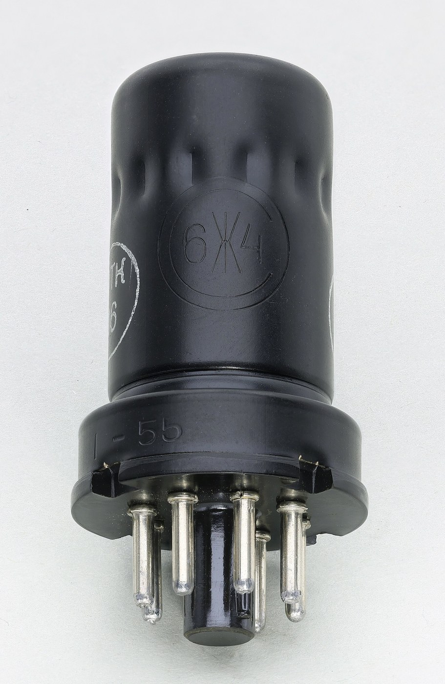


The Screen Grid and the Pentode
ہدایات
Measure the capacitance that causes the trouble
Measure the capacitance that causes the trouble
Find the offending component, which is not a component at all.
- With a triode valve out of circuit and cold, measure the capacitance between anode and grid with an LCR meter.
- Record it — it will be a few picofarads.
- Now compute what that capacitance appears as at the input, multiplied by the stage gain plus one.
A few picofarads of anode-grid capacitance behaves like tens or hundreds of picofarads across the input, because the anode swings in the opposite direction to the grid and by a much larger amount. This multiplication is the Miller effect, and it means the input capacitance of an amplifier depends on its own gain.
Two consequences follow immediately, and both were serious. The huge effective input capacitance detunes and damps the tuned circuit feeding the stage. And because the feedback path exists at all, with the right phase shift the stage will oscillate on its own.
Neutralisation was the pre-1926 workaround: deliberately feed back an equal and opposite signal through a small adjustable capacitor to cancel the unwanted path. It works, and it must be re-trimmed for every valve, every frequency and every replacement. That fragility is what made the screen grid worth inventing.اس مرحلے کے لیے مواد:
 والو ساکٹ1 سیٹ
 کپیسیٹر کِٹ1 کٹ
درکار اوزار:
 میز والا LCR میٹر
 تجربہ گاہی درجے کا ڈیجیٹل ملٹی میٹر
 ڈیجیٹل ورنیئر کیلیپر ۶ انچ
 شفاف حفاظتی عینک
 ٹرائیوڈ والو
Add a screen grid and shield the anode from the grid
Add a screen grid and shield the anode from the grid
Fit a tetrode and repeat every measurement.
- Build the same amplifier stage using a tetrode, with the screen grid connected to a steady positive supply and bypassed to earth by a good capacitor.
- Measure anode-to-control-grid capacitance again.
- Measure the stage gain.
- Try to make it oscillate by increasing the load impedance.
Anode-grid capacitance falls by a factor of hundreds, gain rises by a factor of tens, and the stage is far harder to provoke into oscillating. The screen is doing two jobs at once: electrostatically it is an earthed shield between the two electrodes, and electrically it accelerates electrons past the control grid so the anode voltage barely influences the current at all.
The bypass capacitor is not optional. The screen must be at earth potential for signals even while sitting at a high DC voltage. Leave it unbypassed and the screen swings with the signal, the shielding evaporates, and you have an expensive triode.
This is a genuinely elegant kind of fix — the problem was geometric, so the solution is a piece of geometry rather than a compensating circuit. Compare it with neutralisation, which cancels a fault rather than removing it, and note which one survived.اس مرحلے کے لیے مواد:
 ٹیٹروڈ والو1 سیٹوالو ساکٹ1 سیٹکپیسیٹر کِٹ1 کٹ
 مزاحمت کاروں کا سیٹ1 کٹ
 سوراخ دار بورڈ / نمونہ بورڈ1 ٹکڑا
 ٹانکے کا تار1 reel
درکار اوزار:
میز والا LCR میٹر آسیلوسکوپ
 سگنل جنریٹرتجربہ گاہی درجے کا ڈیجیٹل ملٹی میٹر
 قابلِ ترتیب میز کی بجلی سپلائی
 ٹانکا لگانے کا اسٹیشنشفاف حفاظتی عینک
Find the kink, where the tetrode misbehaves
Find the kink, where the tetrode misbehaves
The tetrode introduced a new fault, and its shape on the curve tells you exactly what it is.
- Plot anode current against anode voltage at a fixed control-grid voltage, sweeping the anode from zero upward.
- Pay close attention to the region where anode voltage is below the screen voltage.
- Mark any region where current FALLS as voltage RISES.
There is a dip — a region of negative resistance — where increasing the anode voltage decreases the anode current. The cause is secondary emission: electrons arrive at the anode fast enough to knock further electrons out of its surface, and while the anode is at a lower potential than the screen, those knocked-out electrons are collected by the SCREEN instead of returning. Current that should have gone to the anode goes to the screen, so anode current falls.
A negative-resistance region is not merely untidy. It can sustain oscillation on its own — the dynatron oscillator was built deliberately on this effect — and it badly distorts an amplifier whose signal swings into that region.
So the tetrode traded one instability for another. Worth noting as a pattern: a fix that introduces a new mechanism usually introduces a new failure mode with it, and the second one is often discovered later and in service.اس مرحلے کے لیے مواد:
مزاحمت کاروں کا سیٹ1 کٹ خانہ دار کاغذ1 pad
درکار اوزار:
آسیلوسکوپتجربہ گاہی درجے کا ڈیجیٹل ملٹی میٹرقابلِ ترتیب میز کی بجلی سپلائیسگنل جنریٹرشفاف حفاظتی عینکAdd a suppressor grid and get the pentode
Add a suppressor grid and get the pentode
Fix the secondary-emission problem with a third grid, and understand why it is at earth.
- Build the same stage with a pentode, its suppressor grid connected to the cathode.
- Repeat the anode current against anode voltage sweep.
- Compare the curve with the tetrode’s.
The kink is gone; the curve rises and then flattens into a long horizontal plateau. The suppressor sits between screen and anode at cathode potential — negative relative to both — so it repels the slow secondary electrons knocked out of the anode and returns them to the anode, while the fast primary electrons from the cathode sail straight through.
The flat plateau is worth dwelling on: anode current is now almost independent of anode voltage. That is very nearly a constant-current source controlled by the grid, which is exactly what an amplifier wants — enormous voltage gain, and a stage whose behaviour barely depends on its load.
Reverse-engineering note: the beam tetrode reaches the same result differently, using beam-forming plates to create a dense space charge between screen and anode that repels secondaries without a third grid. Two mechanisms, one goal — and both are still in production for audio amplifiers, where their different distortion characters are argued over to this day.اس مرحلے کے لیے مواد:
 پینٹوڈ والو1 سیٹوالو ساکٹ1 سیٹمزاحمت کاروں کا سیٹ1 کٹکپیسیٹر کِٹ1 کٹخانہ دار کاغذ1 pad
درکار اوزار:
آسیلوسکوپتجربہ گاہی درجے کا ڈیجیٹل ملٹی میٹرقابلِ ترتیب میز کی بجلی سپلائیسگنل جنریٹرٹانکا لگانے کا اسٹیشنشفاف حفاظتی عینکBuild a stable RF amplifier and prove the point
Build a stable RF amplifier and prove the point
Put the pentode to work in the job the triode could not hold.
- Build a tuned RF amplifier stage using the pentode, with a high-Q tuned circuit as its anode load.
- Measure gain and check the tuned circuit’s Q with the stage running.
- Increase the load impedance progressively and see how far you can push gain before instability appears.
- Repeat the whole test with a triode in an equivalent circuit.
The pentode gives far more gain before oscillating, and it loads the tuned circuit far less, so selectivity survives. That combination is what made multi-stage IF strips practical — and therefore what made the superheterodyne buildable as a mass-market product rather than a laboratory curiosity.
Layout matters more than the schematic here. At radio frequencies a centimetre of wire is an inductor and two parallel wires are a capacitor, so a screen-grid valve carefully shielded internally can still oscillate if input and output wiring run side by side on the board. The metal cans, chassis partitions and short direct leads in old radios are not tidiness — they are the parts of the circuit that do not appear on the diagram.اس مرحلے کے لیے مواد:
 روغن چڑھی تانبے کی تار10 mکپیسیٹر کِٹ1 کٹمزاحمت کاروں کا سیٹ1 کٹ
 ایلومینیم کی چادر1 شیٹ
درکار اوزار:
آسیلوسکوپسگنل جنریٹر طیف تجزیہ کار / FFT سافٹ ویئرمیز والا LCR میٹرتجربہ گاہی درجے کا ڈیجیٹل ملٹی میٹرقابلِ ترتیب میز کی بجلی سپلائیٹانکا لگانے کا اسٹیشن
 ریتیوں کا سیٹشفاف حفاظتی عینک
مواد
10- 1 سیٹپلیس ہولڈر
- 1 کٹپلیس ہولڈر
- 1 سیٹپلیس ہولڈر
- پلیس ہولڈر
- پلیس ہولڈر
- 1 reelپلیس ہولڈر
- 1 padپلیس ہولڈر
- 1 سیٹپلیس ہولڈر
- پلیس ہولڈر
- 1 شیٹپلیس ہولڈر
درکار اوزار
11- پلیس ہولڈر
- پلیس ہولڈر
- پلیس ہولڈر
- پلیس ہولڈر
- پلیس ہولڈر
- پلیس ہولڈر
- پلیس ہولڈر
- پلیس ہولڈر
- پلیس ہولڈر
- پلیس ہولڈر
- پلیس ہولڈر
متعلقہ بلیو پرنٹ
یہ بلیو پرنٹ علم بانٹتے ہیں — تکنیک، مواد یا اصول


CC0 پبلک ڈومین
یہ بلیو پرنٹ CC0 کے تحت جاری کیا گیا ہے۔ آپ اجازت لیے بغیر اس کام کو نقل، ترمیم، تقسیم اور کسی بھی مقصد کے لیے استعمال کرنے کے لیے آزاد ہیں۔
میکر کی حمایت کریں ان کے بلیو پرنٹ کے ذریعے پروڈکٹس خرید کر جہاں وہ میکر کمیشن وینڈرز کی طرف سے مقرر، کماتے ہیں، یا اس بلیو پرنٹ کی نئی تکرار بنائیں اور آمدنی شیئر کرنے کے لیے اسے اپنے بلیو پرنٹ میں کنکشن کے طور پر شامل کریں۔