Współpraca
SZTUKA
Piękno i dobre samopoczucie
RZEMIOSŁO
KULTURA I HISTORIA
ROZRYWKA
ŚRODOWISKO
JEDZENIE I NAPOJE
INŻYNIERIA ODWROTNA
NAUKI
LEKKOATLETYKA
TECHNOLOGIA
URZĄDZENIA DO NOSZENIA
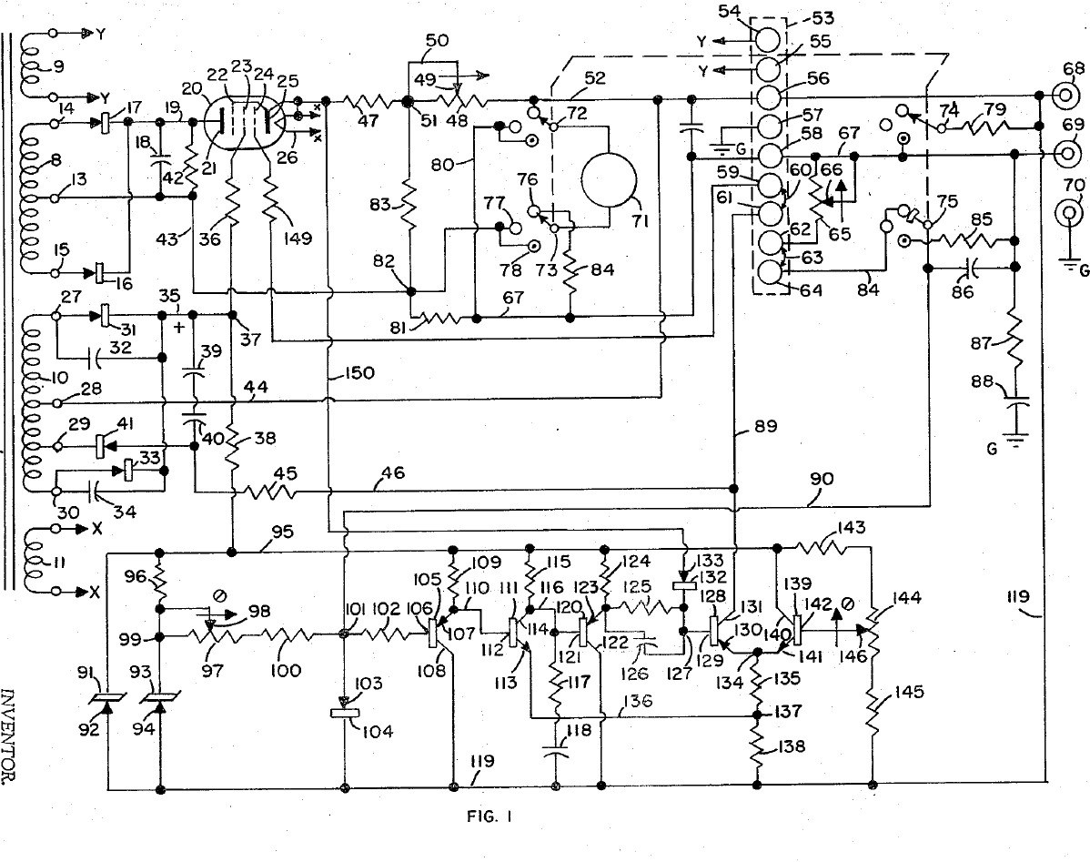


Bench Power Supply: Regulated, with Adjustable Current Limit and a Pentode Pass Tube (Gately, Forbro, US 3,243,690, 1966)
An adjustable bench supply that holds its output voltage steady and lets you set the most current it will deliver, so a circuit under test cannot be damaged. A pentode tube in series with the output is the regulator; a bridge with Zener references and a five-transistor amplifier keeps the output equal to the setting of one knob. A meter switch reads volts, amps, and the current limit, which can be set without disturbing the voltage.
Result: a regulated DC bench supply with adjustable current limiting.
Source: J. R. Gately (Forbro Design), US 3,243,690 (1966). Unknown: all component values and the output rating. Picture: the patent drawing.
Zaawansowany
Unknown
Instrukcje
1
1
Wire the mains side
Wire the mains side
In a case, wire the power cord through a switch and a fuse to the primary of a transformer with four secondaries, and put a neon lamp across the primary to show the supply is on. One secondary (6.3 V) goes to two terminals for outside use, one heats the pentode, one is the main supply and one the bias supply. Ours: the case. Not given: the other winding voltages.
Materiały do tego kroku:
 Obudowa aluminiowa1 case
 Przewód giętki z wtyczką1 sztuka
 Przełącznik dźwigniowy1 sztuka
 Bezpiecznik topikowy1 sztuka
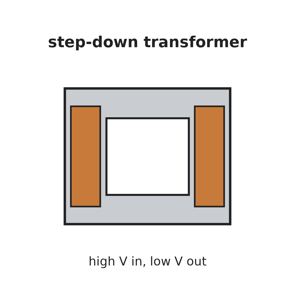 Transformator obniżający napięcie1 four secondaries
 Lampka neonowa sygnalizacyjna1 sztuka
 Zacisk bananowy2 6.3 V terminals
Potrzebne narzędzia:
 Wiertarka ręczna
 Zestaw wkrętaków
2
2
Build the rectifiers
Build the rectifiers
Rectify the centre-tapped main winding with two rectifiers and smooth it with a capacitor. From the bias winding make two more supplies: one through two rectifiers with by-pass capacitors to a smoothing capacitor, for the pentode's screen and the reference circuit; the other through one rectifier and a capacitor, for the pentode's grid bias. Not given: the values.
Materiały do tego kroku:
 Dioda5 rectifiers
 Kondensator elektrolityczny3 smoothing
 Zestaw kondensatorów1 by-pass
 Drut lutowniczy1 as needed
Potrzebne narzędzia:
 Lutownica
3
3
Fit the pass tube and reference
Fit the pass tube and reference
Put the pentode in series with the positive output: plate to the main supply, cathode through two current-sensing resistors (one fixed, one adjustable) to the + output terminal; suppressor tied to the cathode, screen fed through a resistor. Build the reference: a Zener fed through a resistor feeds a second Zener at constant current, giving a fixed voltage. Against it set two resistors and the voltage-control variable resistor: the output voltage is proportional to that resistor's setting. Not given: the tube type and values.
Materiały do tego kroku:
 Lampa pentodowa1 series pass tube
 Dioda Zenera2 sztuk
 Opór elektryczny1 zestaw
 Reostat2 voltage control, current-limit rangeZacisk bananowy2 output + and -Drut lutowniczy1 as needed
Potrzebne narzędzia:
Lutownica4
4
Build the error amplifier and current limit
Build the error amplifier and current limit
Build a five-transistor amplifier that drives the pentode's grid to keep the bridge balanced: a PNP emitter follower, an NPN stage, a PNP emitter follower with a resistor-capacitor roll-off against oscillation, a PNP driver whose base resistor has a capacitor across it for quick response, and an NPN clamp whose base is set by a potentiometer. Feed the voltage across the current-sensing resistors to the driver's base through a diode: above the limit it takes over and turns the pentode down. Choose the fixed sensing resistor to limit at about 125 % of rated current, trim with the potentiometer, and use the adjustable one to set lower limits. Not given: the transistor types and values.
Materiały do tego kroku:
 Tranzystor PNP3 sztuk
 Tranzystor NPN2 sztukDioda1 sztuka
 Potencjometr1 sztukaZestaw kondensatorów1 roll-off, speed-upOpór elektryczny1 zestawDrut lutowniczy1 as needed
Potrzebne narzędzia:
Lutownica5
5
Fit the meter and use it
Fit the meter and use it
Fit a meter with a four-pole, three-position switch. Position 1 reads output volts through a multiplier resistor; position 2 reads current across a shunt in the negative line; position 3 (spring-return) puts a load resistor across the output and swaps a fixed resistor for the voltage control, so you can turn the limit control until the current limits at the value you want, without touching the voltage setting. Release the switch and use the supply.
Materiały do tego kroku:
 Miernik tablicowy magnetoelektryczny1 sztuka
 Przełącznik obrotowy1 4-pole, 3-positionOpór elektryczny1 multiplier, shunt, load resistors
 Nieznany materiał1 terminal strip
Potrzebne narzędzia:
LutownicaZestaw wkrętakówMateriały
21- 1 caseZastępnik
- 1 sztukaZastępnik
- Zastępnik
- 1 sztukaZastępnik
- 1 four secondariesZastępnik
- 1 sztukaZastępnik
- Zastępnik
- 1 sztukaZastępnik
- 3 smoothingZastępnik
- 1 roll-off, speed-upZastępnik
- 3 as neededZastępnik
- 1 series pass tubeZastępnik
- 2 sztukZastępnik
- 1 multiplier, shunt, load resistorsZastępnik
- 2 voltage control, current-limit rangeZastępnik
- 3 sztukZastępnik
- 2 sztukZastępnik
- Zastępnik
- Zastępnik
- 1 4-pole, 3-positionZastępnik
- 1 terminal stripZastępnik
Według tego planu powstaje

CC0 Domena publiczna
Ten plan jest udostępniany na licencji CC0. Możesz go swobodnie kopiować, modyfikować, rozpowszechniać i wykorzystywać do dowolnych celów, bez konieczności uzyskiwania zgody.
Wesprzyj Makera kupując produkty przez jego plan, za co zarabia Prowizja Makera ustalony przez sprzedawców, lub stwórz nową iterację tego planu i dołącz go jako połączenie w swoim własnym planie, aby dzielić się przychodami.