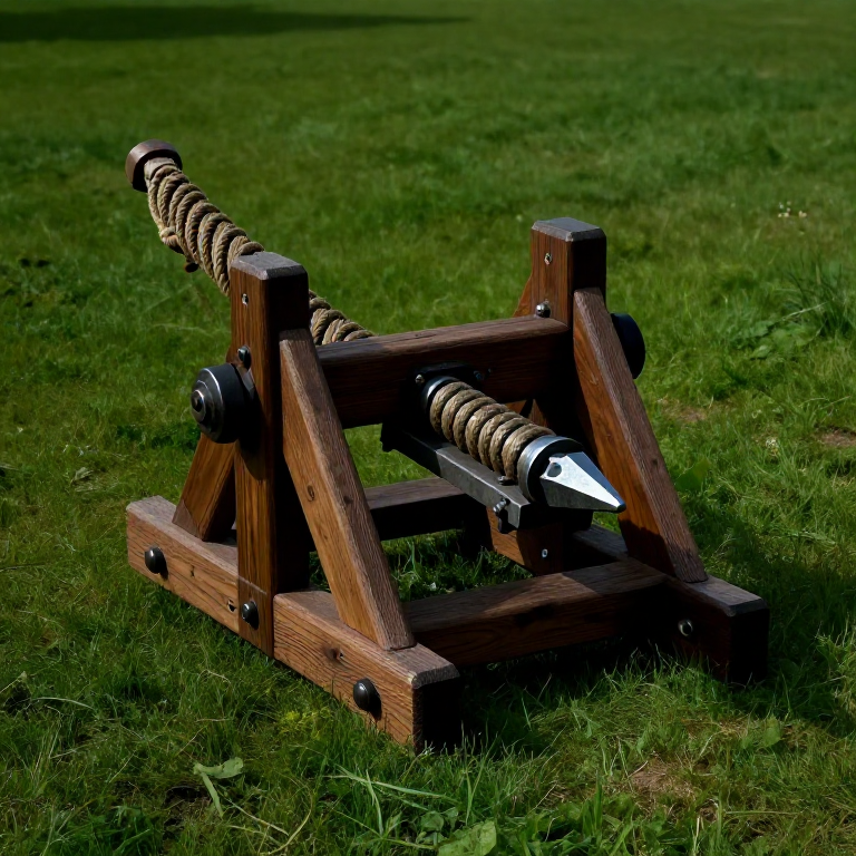
Building a Roman Ballista — The Torsion-Powered Bolt Thrower
The ballista (from Greek ballein, to throw) was the Roman artillery piece par excellence: a precision torsion-spring weapon that hurled iron-tipped bolts (and sometimes stones) with flat trajectories and remarkable accuracy. Unlike the later trebuchet, which relied on gravity and a swinging counterweight, the ballista stores energy in twisted skeins of rope or sinew — the torsion principle. Twisting a bundle of fibres stores immense elastic energy; releasing a lever arm against that tension converts the stored energy into kinetic energy at high speed.
Roman ballistae were weapons of precision as much as power. A trained crew could hit a man-sized target at 150 metres with consistency. At the siege of Jotapata in 67 AD, the Jewish historian Josephus (an eyewitness) recorded that ballista bolts passed through groups of defenders, skewering three men with a single shot. Julius Caesar deployed ballistae from ships to cover beach landings in Britain — the Romans invented naval fire support using ballistae mounted on galleys. Each legion had a complement of 60 ballistae and 10 larger stone-throwing onagers, making the Roman army the first to field systematic heavy artillery as a standard component of field forces.
The key engineering insight of the ballista is the frame of wood and iron that holds the torsion spring bundles under extreme tension. The springs (modioli) consist of bundles of horse sinew, human hair, or animal gut — all materials with excellent elastic properties. The tension is adjusted by rotating the spring anchor caps (epizygis) and locking them with a pin through a ratchet ring. This adjustability allows the crew to tune the weapon's power and to compensate for changes in humidity that affect fibre elasticity. Roman artillery manuals (such as the Belopoiika of Heron of Alexandria) specify frame dimensions by calibre (the diameter of the spring bundle) using a fixed ratio system that scaled the weapon proportionally.
Instrukcje
Calculate the calibre from the intended bolt weight
Calculate the calibre from the intended bolt weight
Roman ballistae were designed using a proportional system based on the calibre (D) — the diameter of the torsion spring bundle in dactyls (Roman finger-widths, approximately 19.3 mm each). According to Heron of Alexandria's Belopoiika, the calibre for a bolt-throwing ballista is determined by: D = 1.1 × cube root of (bolt length in dactyls). For a standard legionary ballista bolt of 60 cm (31 dactyls), this gives D = 1.1 × ∛31 ≈ 3.46 dactyls ≈ 67 mm. All other frame dimensions scale directly from this single calibre measurement. A field ballista typically had a calibre of 50–90 mm and was operated by a crew of 5–10 men.
Cut and shape the main frame timbers
Cut and shape the main frame timbers
The ballista frame consists of two vertical stanchions (side plates) and a horizontal crossbar (transsom) forming a U-shape, plus a projecting trough (the shooting channel) down the centreline. All structural timbers are cut from dense, knot-free hardwood — ash, oak, or elm. The stanchion height is 7× the calibre (7D = approximately 47 cm for our example). The overall frame width is 6.5D from outside to outside. The shooting trough is 18D long, attached to the centre of the crossbar and running forward. Mortise-and-tenon all joints and reinforce with iron straps and bolts — the frame will experience violent shock forces on every shot and must not flex or loosen.
Materiały do tego kroku:
 Hardwood Block12 sztuk
 Iron Nails60 sztuk
Tools needed:
 Hand Saw
 Hammer (2 kg)
Build the two spring (modioli) frame housings
Build the two spring (modioli) frame housings
The torsion spring housings (modioli) are rectangular wooden boxes, one on each side of the frame, each containing a vertical hole of diameter D (the calibre) through which the spring bundle passes. The housing consists of two heavy wooden plates (the capital and the base plate of each spring frame, each approximately 3D thick) connected by two vertical stanchions of the spring box. Iron reinforcement plates line the interior of the spring hole to prevent the wood from splitting under the enormous torsion force. Drill the spring hole vertically through the assembled housing using an auger of the correct calibre diameter. The two spring housings must be mounted symmetrically on the main frame — any asymmetry produces an asymmetric throw.
Tools needed:
 Awl
AwlWind the torsion spring bundles
Wind the torsion spring bundles
Thread the torsion spring material (sinew cord, horsehair rope, or strong linen rope as a modern substitute) through the spring holes in figure-eight turns, filling the calibre hole until the bundle is packed solid. Animal sinew is the original and best material — it stores more elastic energy per unit weight than any plant fibre, and ancient writers noted that Roman springs used sinew from female deer (cerva) or horse tendons for their superior springback. Modern testing shows sinew stores approximately twice the energy of hemp rope at the same stress level. Wind sufficient material to fill the calibre hole tightly when all turns are in place — approximately 50-80 individual strands for a 67 mm calibre hole.
Materiały do tego kroku:
 Hemp Cord20 metrów
Insert and fit the arm through the torsion bundle
Insert and fit the arm through the torsion bundle
Each spring bundle receives one throwing arm — a straight hardwood lever arm approximately 8D long (54 cm for our calibre), 1.5D wide, and 1D thick. The arm is inserted horizontally through the spring bundle at the bundle's mid-height. The two arms on each side of the frame thus project inward toward the centreline of the weapon. In the rest position (unloaded), both arms are pulled forward by the spring tension, pointing toward the front of the weapon at approximately 20–30 degrees from vertical. When cocked, the arms are winched backward until they point rearward — this is the stored-energy position.
Materiały do tego kroku:
 Hardwood Shaft (2m)2 sztuk
Fit the spring tension adjustment caps (epizygis) with ratchet rings
Fit the spring tension adjustment caps (epizygis) with ratchet rings
At the top and bottom of each spring hole, fit a rotating disc (epizygis) that the spring bundle wraps around. The disc has peripheral holes (approximately 16–20 holes around the circumference) that align with a fixed locking pin on the frame. Rotating the disc by one hole position twists the entire spring bundle by one hole-increment, increasing tension. Fit a ratchet arrangement so the disc cannot unwind under load — a spring-loaded iron pawl drops into the peripheral holes. To adjust tension: release the pawl, rotate the disc the desired amount with an iron lever, and let the pawl re-engage. This mechanism allows each spring to be individually tuned for equal tension on both sides — essential for a straight-flying bolt.
Attach the bowstring between the two arm tips
Attach the bowstring between the two arm tips
Connect the two arm tips with a short, very strong bowstring of twisted sinew or thick linen cord. The string connects the two arm tips and is the direct interface between the spring mechanism and the bolt. The string must be short enough to reach easily from one arm tip to the other when the arms are in the fired (forward) position, but long enough not to be under tension in that position — all tension comes from the torsion springs, not the string geometry. The string centreline must lie exactly along the shooting trough centreline. Attach the string using iron hooks or notches carved into the arm tips — the string is under several hundred kilograms of pull force when cocked and must not slip.
Build and fit the cocking winch (epagogeus)
Build and fit the cocking winch (epagogeus)
Cocking the ballista (pulling the bowstring from the rest position to the cocked position against the spring resistance) requires mechanical advantage — even a small ballista needs 200–400 kg of force. Build a winch mechanism: a horizontal axle (the epagogeus) with a crank handle on one side and a ratchet drum on the other, mounted in brackets at the rear of the shooting trough. A rope or chain from the drum connects to a claw (the chelonium — 'tortoise') that grips the bowstring. Winding the crank hauls the bowstring back along the trough to the trigger position, with the ratchet holding the load at each increment. The mechanical advantage of the winch (handle radius to drum radius ratio of approximately 4:1) reduces operator effort to a manageable 50–100 kg.
Install the trigger mechanism (katastates)
Install the trigger mechanism (katastates)
The trigger (katastates) holds the cocked bowstring and releases it cleanly when the operator commands. The simplest effective design is a pivoting iron hook mounted in a slot in the shooting trough — the hook engages a loop in the bowstring when cocked and releases when the operator pulls a lever that rotates the hook downward into the slot. The trigger must be absolutely secure under the spring tension load yet release cleanly and instantaneously — any hesitation allows the string to drag against the hook, pushing the bolt sideways and causing an inaccurate shot. Test the trigger dry (without a bolt) many times before loading to ensure reliable, consistent release.
Make the trough guide rail for the bolt
Make the trough guide rail for the bolt
The shooting trough is a U-shaped channel that guides the bolt from its resting position at the trigger to the muzzle of the weapon. The trough must be perfectly straight — any bend or twist deflects the bolt. Line the trough with a smooth groove just wide enough to accept the bolt's shaft (approximately 25–30 mm for a standard bolt). The groove must be exactly centred on the trough width so the bowstring contacts the bolt butt perfectly centrally. Smooth the groove with a chisel and sandstone and coat with tallow or beeswax to minimize friction. The bolt rests in the groove under gravity only — do not fit any retention clip that could interfere with the bolt's departure.
Mount the ballista on a rotating traverse base
Mount the ballista on a rotating traverse base
Field ballistae were mounted on a wooden base that allowed rotation in azimuth (horizontal pointing) and elevation adjustment. Build a simple traversing base: a heavy lower platform (fixed) with a rotating upper platform (pivoting on an iron pin through the centre). The weapon frame bolts onto the upper platform. For elevation adjustment, the weapon frame pivots on a horizontal axle at the rear of the lower frame — raising or lowering the front changes elevation. Locking wedges hold the elevation once set. Roman ballista mounts also incorporated an aiming sight: a simple iron pin at the muzzle end and a V-notch at the operator position, allowing repeatable target acquisition.
Make the iron-tipped bolts (katrabolos)
Make the iron-tipped bolts (katrabolos)
Ballista bolts are shorter and heavier than arrows — approximately 60–75 cm long, with a shaft diameter of 25–30 mm. The shaft is turned or split from straight-grained ash wood. At the nose, hammer-forge an iron pyramidal tip approximately 8 cm long and press-fit it onto the shaft, secured with iron rivets or wrapped iron wire. At the tail, cut three or four fletching vanes from stiff wood or bronze sheet — not feathers, which are too fragile for the ballista's violence — and glue and bind them to the shaft at 120-degree intervals. The bolt must be perfectly straight when rolled on a flat surface. Any warp will cause it to corkscrew erratically in flight. A quality ballista bolt with iron tip weighs approximately 150–200 grams.
Calibrate spring tension and conduct test firing
Calibrate spring tension and conduct test firing
Set up in an open field with a minimum 200-metre clear range. Set both torsion springs to the same tension position on the ratchet rings (the same notch number, counted from the zero tension position). Cock the weapon, place a bolt in the trough, aim at a stable target at 100 metres, and fire. Note where the bolt strikes — if it goes right, the left spring has more tension; if it goes left, increase left spring or decrease right spring by one ratchet position. Adjust spring tension by equal increments on both sides to increase or decrease power. A well-tuned ballista of 67 mm calibre should achieve a range of 150–200 metres against a man-sized target with good accuracy after a few test rounds to establish zero.
Materiały
4- 12 sztukPlaceholder
- 60 sztukPlaceholder
- 2 sztukPlaceholder
Materiały z połączonych planów
Powiązane blueprinty
Te blueprinty dzielą się wiedzą — technikami, materiałami lub zasadami
Related blueprints
Other builds that share materials, tools, or techniques with this one.
CC0 Domena publiczna
Ten plan jest udostępniany na licencji CC0. Możesz go swobodnie kopiować, modyfikować, rozpowszechniać i wykorzystywać do dowolnych celów, bez konieczności uzyskiwania zgody.
Wesprzyj Makera kupując produkty przez jego plan, za co zarabia Prowizja Makera ustalony przez sprzedawców, lub stwórz nową iterację tego planu i dołącz go jako połączenie w swoim własnym planie, aby dzielić się przychodami.