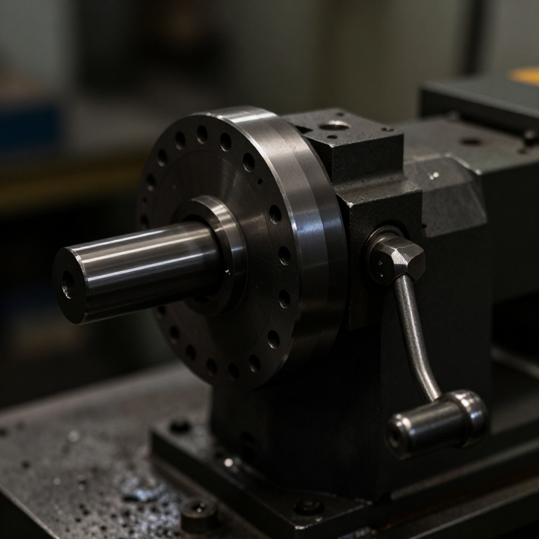


Dividing Head
Instrukcje
Understand the 40:1 arithmetic before building
Understand the 40:1 arithmetic before building
The ratio decides which divisions are possible. Work it out first.
- With a 40:1 worm, crank turns per division = 40 ÷ (number of divisions).
- For 8 divisions: 40 ÷ 8 = 5 full turns — no index plate needed.
- For 24 divisions: 40 ÷ 24 = 1 and 2/3 turns — needs a plate with holes divisible by 3.
- For 7 divisions: 40 ÷ 7 = 5 and 5/7 turns — needs a circle of 7, 14, 21 or 28 holes.
- Tabulate the crank movement for 3, 4, 5, 6, 8, 10, 12, 16, 20, 24 and 32 divisions.
Why 40 became standard. Forty factorises well — 2, 4, 5, 8, 10, 20 all divide it exactly — so a large number of common divisions need whole turns or simple fractions. That is a deliberate choice by whoever settled the convention, not an accident.
Your table tells you which hole circles the index plates must carry. Build the plates to the table, not the other way round.Materiały do tego kroku:
 Papier milimetrowy1 pad
Potrzebne narzędzia:
 Suwmiarka cyfrowa 6 cali
 Kątownik nastawny
Build the worm and wheel
Build the worm and wheel
Forty teeth on the wheel, one start on the worm.
- Cut a 120 mm wheel blank from 18 mm plywood faced with 6 mm aluminium.
- Mark 40 teeth around it — 9 degrees apart — and cut the tooth spaces.
- Use a length of M12 threaded rod as the worm: a single-start thread is exactly what a worm is.
- Mount the worm in two 608 bearings in plywood blocks so it meshes with the wheel rim.
- Fix the blocks with M5 × 40 socket head cap screws × 4, M5 flat washers × 8 and M5 hex nuts × 4, using slotted holes to set mesh depth.
Modern build spec (derived). M12 threaded rod as a worm is a genuinely useful shortcut — the thread pitch sets the tooth pitch, so cut the wheel teeth to match your rod's pitch rather than to a nominal figure. Commercial heads use a hardened ground worm and a bronze wheel, chosen because bronze wears in preference to the expensive worm.
Slotted mounting holes for mesh depth, exactly as on the rack and pinion. Adjustable is not a luxury here — the correct depth is found by feel with the mechanism assembled.Materiały do tego kroku:
 Sklejka z brzozy bałtyckiej1 arkusz
 Płaskownik aluminiowy1 sztuka
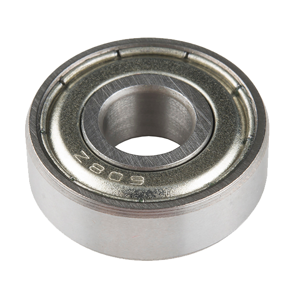 Ball Bearing - Non-Flanged (8mm Bore, 22mm OD)4 sztuk
 Podkładka płaska8 sztuk
 Nakrętka sześciokątna4 sztuk
Potrzebne narzędzia:
 Wyrzynarka
 Piłka włosowa
 Zestaw pilników
 Wiertarko-wkrętarka akumulatorowa
 Zestaw wiertełSuwmiarka cyfrowa 6 cali
Drill the index plates accurately
Drill the index plates accurately
The plate holes carry the fractional turns, so their spacing is the instrument's accuracy.
- Cut two 140 mm discs from 6 mm aluminium.
- On the first, lay out concentric circles of 15, 16, 17, 18, 19 and 20 holes.
- On the second, 21, 23, 27, 29, 31 and 33 holes.
- Step each circle round using dividers set to the chord length rather than measuring angles.
- Centre-punch every hole, then drill 3.2 mm.
Why step with dividers. Walking a divider round a circle distributes the closing error over the whole circle instead of dumping it into the last space, and it lets you detect the error — if the last step does not land on the first mark, adjust and walk again. Measuring each angle separately accumulates error exactly as the protractor does.
The prime-numbered circles are the valuable ones. 7, 11, 13, 17 and 19 divisions are impossible without a hole circle that is a multiple of them, and those are precisely the divisions you cannot fudge by eye.Materiały do tego kroku:
Płaskownik aluminiowy1 sztukaPotrzebne narzędzia:
 PunktakWiertarko-wkrętarka akumulatorowaZestaw wiertełSuwmiarka cyfrowa 6 caliKątownik nastawnyZestaw pilników
Add the crank, detent pin and sector arms
Add the crank, detent pin and sector arms
The sector arms are what stop you miscounting holes, and everyone who omits them regrets it.
- Fit a crank to the worm shaft with an M6 × 30 hex bolt and M6 flat washers × 2.
- Mount a spring-loaded detent pin on the crank to drop into the plate holes.
- Make two thin sector arms pivoting on the plate's centre, clamped together by an M5 × 20 socket head cap screw and M5 flat washer with light friction.
- Set the arms to span the required number of holes PLUS the one you start in.
Plus one. To advance 7 holes you set the sector arms to enclose 8 holes, because the hole you are sitting in counts as the boundary, not as a step. This off-by-one is the single commonest error in dividing work and it produces a part that is subtly, consistently wrong.
After each division, swing the trailing arm up against the pin, ready for the next. That way you never count holes twice and never lose your place mid-job.Materiały do tego kroku:
Płaskownik aluminiowy1 sztuka Zestaw sprężyn naciskowych1 zestawPodkładka płaska4 sztukNakrętka sześciokątna2 sztuk
Potrzebne narzędzia:
Wiertarko-wkrętarka akumulatorowaZestaw wierteł Zestaw kluczy imbusowychZestaw pilników
 Ramka do piły do metalu z brzeszczotami
Prove errors do not accumulate, and history
Prove errors do not accumulate, and history
The closing test — the only test that matters.
- Mount a disc on the spindle and scribe a mark.
- Index through all 24 divisions, scribing each.
- The 24th step must bring you exactly back to the first mark.
- Now repeat the same 24 divisions using a protractor and 15 degree steps, and compare where the last mark lands.
History. Accurate circular division is one of the hardest problems in early instrument making, and it gated astronomy and navigation directly: a sextant is worthless if its arc is not divided truly. Jesse Ramsden's dividing engine of the 1770s automated it and was so important that the Board of Longitude paid him to publish the design. The workshop dividing head is the same idea in a form a machinist can use.
Its siblings: a protractor reads any angle instantly and accumulates error when stepped. A sine bar sets one angle very accurately but does not step at all. A dividing head steps exactly but only into the divisions its plates allow. Three approaches to angle, and this batch holds all three so the trade can be compared directly.
Honest limit: divisions requiring a prime factor with no matching hole circle are simply impossible on a plain head — that is what differential indexing exists to solve, by gearing the plate itself to rotate slowly as the crank turns.
Potrzebne narzędzia:
Suwmiarka cyfrowa 6 caliKątownik nastawnyMateriały
7- 1 padZastępnik
- 1 arkuszZastępnik
- 1 sztukaZastępnik
- Ball Bearing - Non-Flanged (8mm Bore, 22mm OD)10% prowizji4 sztuk$1.26
- 12 sztukZastępnik
- 6 sztukZastępnik
- 1 zestawZastępnik
Wymagane narzędzia
10- Zastępnik
- Zastępnik
- 1 vendor sell this, none ship to you yetZastępnik
- Zastępnik
- Zastępnik
- 1 vendor sell this, none ship to you yetZastępnik
- Zastępnik
- Zastępnik
- Zastępnik
Powiązane blueprinty
Te blueprinty dzielą się wiedzą — technikami, materiałami lub zasadami
CC0 Domena publiczna
Ten plan jest udostępniany na licencji CC0. Możesz go swobodnie kopiować, modyfikować, rozpowszechniać i wykorzystywać do dowolnych celów, bez konieczności uzyskiwania zgody.
Wesprzyj Makera kupując produkty przez jego plan, za co zarabia Prowizja Makera ustalony przez sprzedawców, lub stwórz nową iterację tego planu i dołącz go jako połączenie w swoim własnym planie, aby dzielić się przychodami.