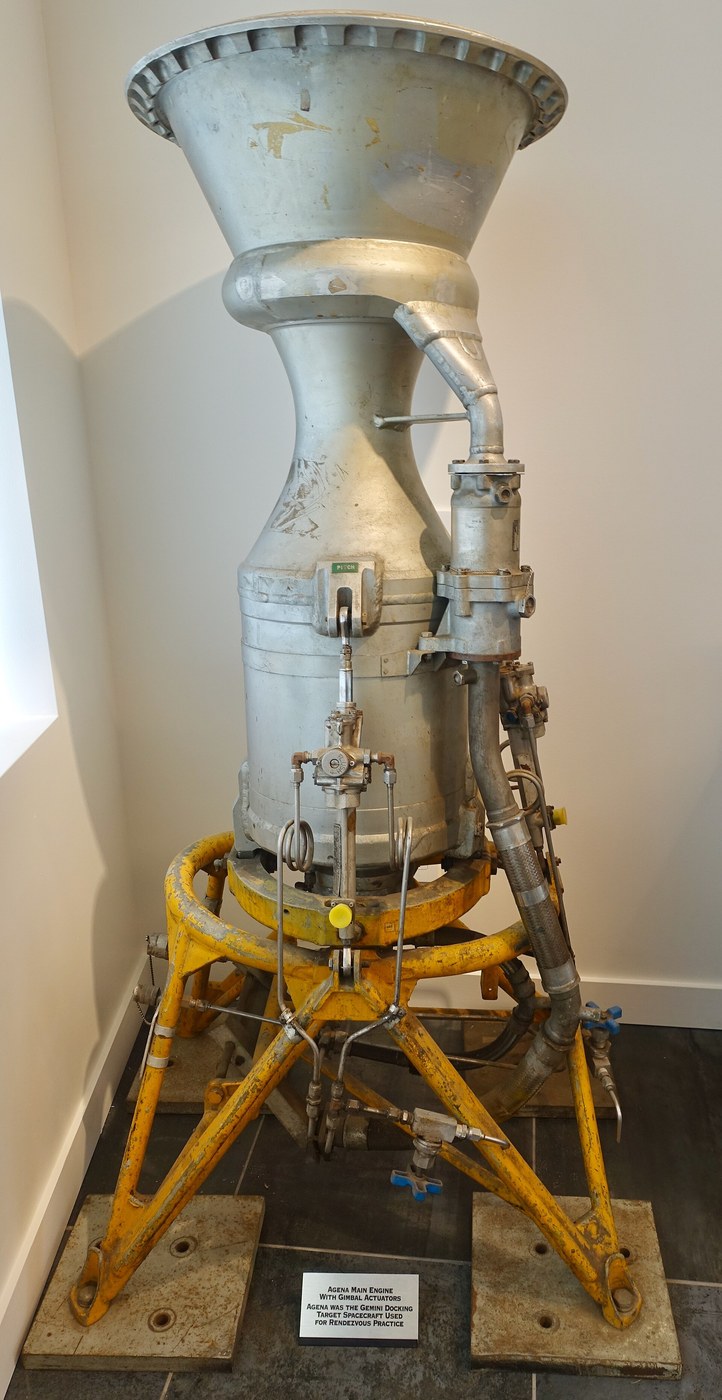


Gimballed Thrust Vectoring
Instrukcje
Prove the instability with a broom handle
Prove the instability with a broom handle
Feel the problem before instrumenting it.
- Balance a broom vertically on your palm and note what you must do to keep it up.
- Try it with your eyes closed.
- Now balance it the other way — hang it from your hand like a pendulum — and let go of the corrections.
Upright, it needs continuous correction and fails instantly without feedback; hanging, it is stable and needs nothing. A rocket under thrust is the upright case: thrust below, mass above, and every degree of tilt generating a moment that increases the tilt.
Notice what your hand actually does — it moves toward the direction of the fall. That is the counter-intuitive part and it is exactly what a gimballed engine does: to correct a tilt to the left, the engine swivels so the thrust pushes the BASE further left, rotating the vehicle back upright about its centre of mass.
This is why a rocket visibly leans and yet flies straight, and why gimbal deflections are small — one or two degrees is plenty, because the lever arm from engine to centre of mass is tens of metres.Materiały do tego kroku:
 Kołek drewniany1 sztuka
Potrzebne narzędzia:
 Smartfon z nagrywaniem w zwolnionym tempie
 Miara zwijana
 Kątomierz cyfrowy
Build a two-axis gimbal ring
Build a two-axis gimbal ring
Two perpendicular hinges give you pitch and yaw from one mount.
- Machine an outer ring that pivots on two opposed bearings about one axis.
- Machine an inner ring pivoting inside it about the perpendicular axis.
- Mount your engine — or a mass dummy with a thrust source — in the inner ring.
- Check the two rotation axes intersect exactly, and that both pass through the engine’s thrust axis.
If the axes do not intersect at a common point, gimballing in one axis translates the engine sideways as well as rotating it, and the two control channels start interfering. That cross-coupling turns an already difficult control problem into a much harder one.
Reverse-engineering note: this is also why the propellant feed lines to a gimballed engine use flexible bellows arranged so their stiffness is symmetric about both axes. An asymmetric duct pushes the gimbal a little in one direction, and the control loop must fight that bias continuously — burning actuator power and margin for nothing.Materiały do tego kroku:
 Płyta aluminiowa1 sztuka
 Łożysko kulkowe4 sztuk
 Kołek stalowy4 sztuk
 Śruby imbusowe M58 sztuk
Potrzebne narzędzia:
 Imadło frezarskie 4 cale
 Tokarka do metalu
 Wiertarka stołowa
 Czujnik zegarowy
 Suwmiarka cyfrowa 6 caliKątomierz cyfrowy
 Klucz dynamometryczny
 Okulary ochronne bezbarwne
Add actuators and measure the response you can command
Add actuators and measure the response you can command
How fast the gimbal can move sets how unstable a vehicle you can fly.
- Fit two actuators — hobby servos are adequate at this scale — one per axis.
- Command a step change and film it, measuring the time to reach the commanded angle.
- Measure the maximum angular rate and the deflection range.
- Measure backlash by commanding a small reversal and seeing how much command produces no motion.
Backlash is the number that will hurt you. Any free play means a region where the loop commands a correction and nothing happens, and a control loop with a dead zone hunts — it overshoots, reverses, waits through the slack, overshoots the other way.
Actuator rate matters just as much. An unstable vehicle diverges at a characteristic rate, and the loop must be able to correct faster than it diverges. If the gimbal is slower than the tipping, no control law will save it.
Real vehicles use hydraulic actuators for exactly this reason, and some — including the Saturn V and the Shuttle — tapped high-pressure propellant from the turbopump as the hydraulic supply, so the engine powered its own steering.Materiały do tego kroku:
 Serwo modelarskie1 zestaw
 Odbiornik RC1 zestaw
 Orczyk sterowy1 zestaw
 Widełki sworzniowe1 zestaw
 Płaskownik aluminiowy1 sztuka
Potrzebne narzędzia:
 Oscyloskop
 Multimetr cyfrowy klasy laboratoryjnej
 Regulowany zasilacz warsztatowySmartfon z nagrywaniem w zwolnionym tempieKątomierz cyfrowySuwmiarka cyfrowa 6 cali
 Stacja lutowniczaOkulary ochronne bezbarwne
The control sketch
The control sketch
Upload this to the board before tuning. It reads the IMU, fuses gyro and accelerometer with a complementary filter, and drives both servos.
Note what the derivative term uses: the gyro rate directly, not a differentiated angle. Differentiating a noisy angle manufactures large spurious commands — the gyro already measures rate cleanly, so use it. The integral term is clamped, because an integrator that keeps accumulating while the servo is already at its limit will wind up and then overshoot badly when the error finally reverses.
Tune in the order Kp, then Kd, then Ki, one at a time, watching the serial telemetry.
Materiały do tego kroku:
 Płytka z mikrokontrolerem1 sztuka
 Inercyjna jednostka pomiarowa (6 osi)1 sztuka
 Przewód montażowy1 reel
Potrzebne narzędzia:
 Komputer z Arduino IDEMultimetr cyfrowy klasy laboratoryjnejOscyloskop
Close a PID loop and tune it on a test stand
Close a PID loop and tune it on a test stand
Now fly the instability on a stand where failure costs nothing.
- Mount the whole assembly on a single-axis pivot so it can tip but not fall.
- Add an inertial sensor measuring angle and angular rate.
- Implement a control loop: proportional to angle error, derivative on rate, a little integral for steady bias.
- Start with proportional only, increase gain until it oscillates, then add derivative and back the gain off.
Proportional alone gives an oscillation that never settles; adding derivative damps it; too much integral makes it sluggish and prone to wind-up. The derivative term is what makes this work — it responds to how fast the error is GROWING, so it starts correcting before the error is large.
Compare with the constant-speed propeller governor from the aviation batch: same negative feedback, same hunting failure when tuned too aggressively. The difference is that a governor is correcting a stable system and this loop is the only thing preventing a tumble.
Filter the derivative term. Rate signals are noisy, and differentiating noise produces large spurious commands that will shake the airframe — several early vehicles had control loops that excited their own structural bending modes, with the sensor reading the vibration the actuator had just created.Materiały do tego kroku:
Inercyjna jednostka pomiarowa (6 osi)1 sztukaPłytka z mikrokontrolerem1 sztukaPrzewód montażowy1 reelPotrzebne narzędzia:
OscyloskopMultimetr cyfrowy klasy laboratoryjnejRegulowany zasilacz warsztatowySmartfon z nagrywaniem w zwolnionym tempieKątomierz cyfrowyStacja lutowniczaOkulary ochronne bezbarwneCompare the alternatives and see why gimbals won
Compare the alternatives and see why gimbals won
Several ways exist to steer a rocket. Measure what each costs.
- Build a jet vane — a small heat-resistant paddle that deflects the exhaust — and measure the side force and the thrust LOST to its drag.
- Model vernier thrusters: small fixed engines used only for control.
- Consider fluid injection: squirting liquid into one side of the nozzle to create an asymmetric shock.
- Tabulate side force, thrust penalty and complexity for each.
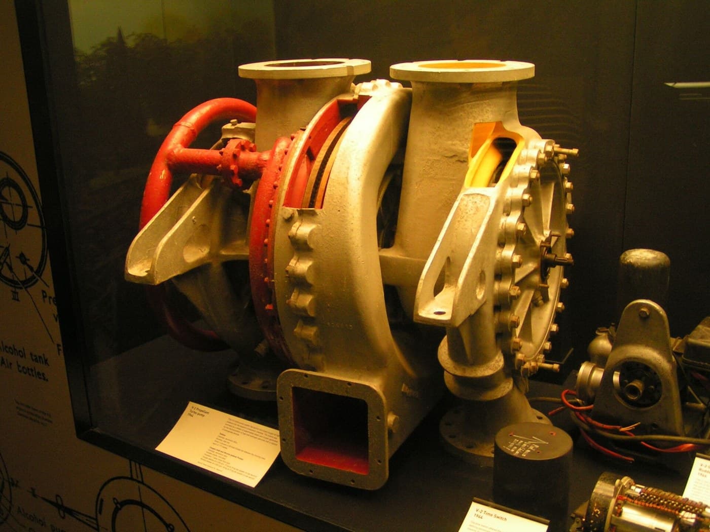
Jet vanes are simple, work from the instant of ignition, and sit in the exhaust stream eroding while stealing a few percent of thrust. Verniers are clean but are extra engines. Fluid injection has no moving parts in the flow and limited authority. Gimbals cost nothing in thrust and demand a mechanism, flexible plumbing and hydraulic power.
The V-2 used graphite jet vanes because gimballing a whole engine in 1942 was beyond the state of the art; they eroded badly and the accuracy suffered. As actuators improved, gimbals took over everywhere the thrust penalty mattered — which is to say, everywhere the rocket equation is watching.
Solid motors cannot gimbal a whole engine easily, so they steer by gimballing just the nozzle on a flexible bearing — a laminated stack of rubber and metal shims, stiff against thrust and compliant in bending. The Shuttle boosters steered exactly that way.Materiały do tego kroku:
 Blok grafitowy1 sztukaPłaskownik aluminiowy1 sztuka
 Papier milimetrowy1 pad
Potrzebne narzędzia:
 Waga sprężynowa
 Termometr na podczerwieńSuwmiarka cyfrowa 6 cali
 Zestaw pilnikówSmartfon z nagrywaniem w zwolnionym tempie
 Waga cyfrowaOkulary ochronne bezbarwne
 Przyłbica ochronna
Materiały
15- 1 sztukaZastępnik
- 1 sztukaZastępnik
- od$1.26
- 4 sztukZastępnik
- 8 sztukZastępnik
- od$8.19
- 1 zestawZastępnik
- 1 zestawZastępnik
- 1 zestawZastępnik
- 1 sztukaZastępnik
- 1 sztukaZastępnik
- Zastępnik
- 1 reelZastępnik
- 1 sztukaZastępnik
- 1 padZastępnik
Wymagane narzędzia
20- 1 vendor sell this, none ship to you yetZastępnik
- Zastępnik
- Zastępnik
- Zastępnik
- Zastępnik
- Zastępnik
- Zastępnik
- Zastępnik
- Zastępnik
- Zastępnik
- Zastępnik
- Zastępnik
- Zastępnik
- Zastępnik
- Zastępnik
- Zastępnik
- Zastępnik
- Zastępnik
Powiązane blueprinty
Te blueprinty dzielą się wiedzą — technikami, materiałami lub zasadami

CC0 Domena publiczna
Ten plan jest udostępniany na licencji CC0. Możesz go swobodnie kopiować, modyfikować, rozpowszechniać i wykorzystywać do dowolnych celów, bez konieczności uzyskiwania zgody.
Wesprzyj Makera kupując produkty przez jego plan, za co zarabia Prowizja Makera ustalony przez sprzedawców, lub stwórz nową iterację tego planu i dołącz go jako połączenie w swoim własnym planie, aby dzielić się przychodami.