Współpraca
SZTUKA
Piękno i dobre samopoczucie
RZEMIOSŁO
KULTURA I HISTORIA
ROZRYWKA
ŚRODOWISKO
JEDZENIE I NAPOJE
INŻYNIERIA ODWROTNA
NAUKI
LEKKOATLETYKA
TECHNOLOGIA
URZĄDZENIA DO NOSZENIA
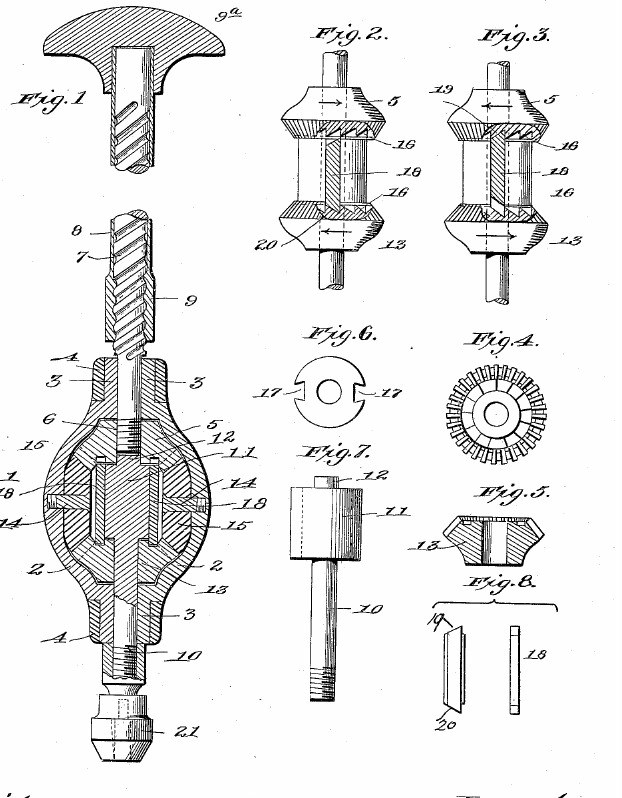


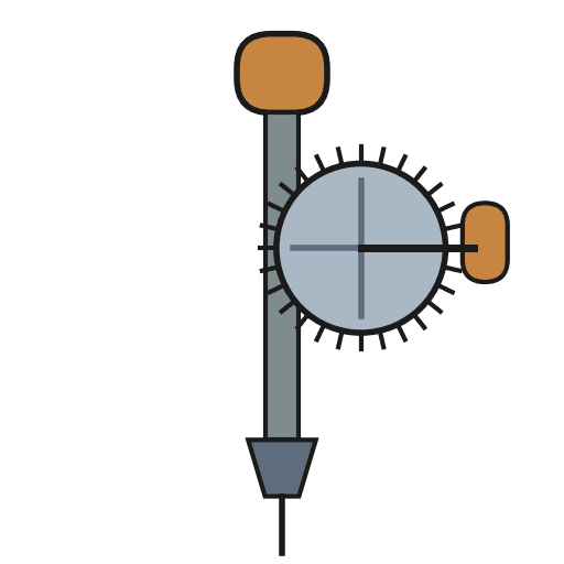
Hand Drill: Double-Acting Push Drill, Spiral Rod and Ratchet Bevel Gears (Olson, US 652,137, 1900)
A hand drill you work by pushing a handle back and forth. The handle's nut runs on a spiral-grooved rod and spins it one way, then the other. Inside a bulb-shaped casing you hold in your other hand, bevel gears and two sliding ratchet bolts turn that back-and-forth spin into steady rotation of the chuck, so the bit cuts on every stroke.
Result: a hand drill that bores continuously in one direction from a push-pull stroke.
Source: J. E. Olson, US 652,137 (1900). Unknown: all materials and sizes. Picture: the patent drawing.
Zaawansowany
Unknown
Instrukcje
1
1
Make the casing
Make the casing
Make two half-egg-shaped shells, each with a half-round neck at both ends. Put them face to face and hold them together with ferrules pushed over the necks: a hollow bulb that fits the hand. Not given: the metal, sizes.
Materiały do tego kroku:
 Nieznany metal1 shells, ferrules
Potrzebne narzędzia:
 Tokarka do metalu
 Nieznane wymiary
2
2
Make the spiral rod and handle
Make the spiral rod and handle
Cut a rod with a steep spiral groove or thread. Fit a tube over it with a nut at its lower end that runs in the spiral, and a handle at its upper end. Not given: the pitch, the handle material.
Materiały do tego kroku:
Nieznany metal1 rod, tube, nut Nieznany materiał1 handle
Potrzebne narzędzia:
Tokarka do metalu Zestaw do gwintowania
3
3
Make the gears and ratchet hub
Make the gears and ratchet hub
Take four bevel wheels: an upper one bored through the centre and fixed on the lower end of the spiral rod, a lower one the same shape and size, and two side wheels that gear them together. Cut a ring of ratchet teeth on the facing sides of the upper and lower wheels, slanted opposite ways. Make a shaft with a hub (barrel) at its top whose tip runs in the bore of the upper wheel; cut two upright dovetail grooves in the hub, each holding a sliding bolt with its two ends bevelled opposite ways, long enough that one end meets one wheel's teeth while the other end is clear of the other wheel. Ours: steel mitre gears.
Materiały do tego kroku:
 Zestaw przekładni stożkowej (stal, 1:1)2 four bevel wheelsNieznany metal1 shaft, hub, two bolts
Potrzebne narzędzia:
Tokarka do metalu Piła do metalu
4
4
Assemble
Assemble
Inside the casing, set the upper wheel with the spiral rod coming out of the top neck, the hub between the wheels, and the lower wheel turning loose on the shaft. Run the two side wheels on screws through the casing wall as their axles. Bring the shaft out of the lower neck and fix a drill chuck on its end. Ours: a drill chuck.
Materiały do tego kroku:
Nieznany metal1 two journal screws Uchwyt wiertarski1 sztuka
Potrzebne narzędzia:
Zestaw do gwintowania5
5
Drill
Drill
Put a bit in the chuck and set it on the mark. Hold the casing still in one hand, pressing lightly toward the work, and push and pull the handle with the other. Each stroke turns the upper and lower wheels opposite ways; the bolts slide over to engage whichever wheel is turning the cutting way, so the bit turns steadily one way.
Potrzebne narzędzia:
 Zestaw wierteł
Materiały
4- 1 two journal screwsZastępnik
- 1 handleZastępnik
- 2 four bevel wheelsZastępnik
- 1 sztukaZastępnik
Wymagane narzędzia
5- Zastępnik
- Zastępnik
- Zastępnik
- Zastępnik
- Zastępnik
Materiały z połączonych planów

Według tego planu powstaje
CC0 Domena publiczna
Ten plan jest udostępniany na licencji CC0. Możesz go swobodnie kopiować, modyfikować, rozpowszechniać i wykorzystywać do dowolnych celów, bez konieczności uzyskiwania zgody.
Wesprzyj Makera kupując produkty przez jego plan, za co zarabia Prowizja Makera ustalony przez sprzedawców, lub stwórz nową iterację tego planu i dołącz go jako połączenie w swoim własnym planie, aby dzielić się przychodami.