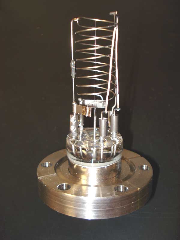


Ionisation Gauge
Instrukcje
Build the three-electrode structure
Build the three-electrode structure
Filament, grid and collector — the same architecture as a triode valve, doing a different job.
- Mount a fine tungsten filament as the electron source.
- Surround it with an open helical grid of wire, which will be held at a positive voltage.
- Place a collector electrode outside the grid.
- Bring three separate feedthroughs out of the envelope.
- Check none of the electrodes can touch another.
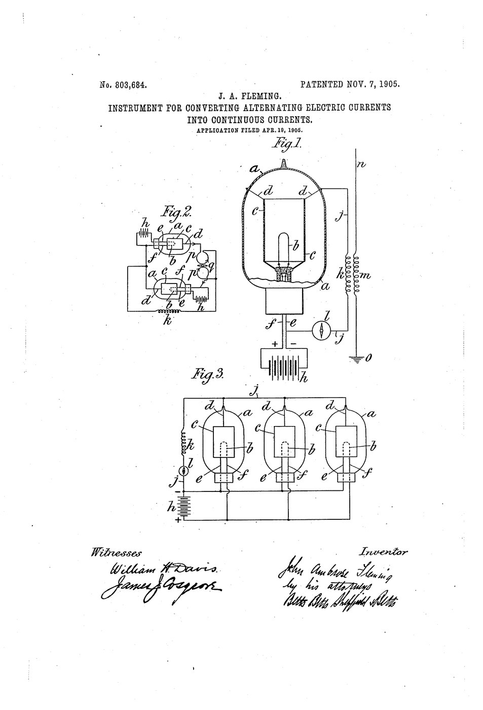
This is a Fleming valve with an extra electrode and an opposite purpose. A valve is built to have as little gas inside as possible so the electron stream is undisturbed; an ionisation gauge is built to measure the small amount that remains by deliberately letting electrons collide with it. The same structure, optimised for opposite ends.
Fine wire everywhere. A thick collector intercepts soft X-rays produced when electrons strike the grid, and those X-rays release electrons from the collector that look exactly like ion current — which sets a false floor to the reading.Materiały do tego kroku:
 Enamelled Copper Wire1 rolka
 Glass Tubing Kit1 zestaw
 Bare Copper Wire 10 AWG1 rolka
Potrzebne narzędzia:
 Digital Multimeter (Lab Grade)
 File Set
 Digital Caliper 6-Inch
 Bench Vise
Set the three voltages correctly
Set the three voltages correctly
Each electrode has a job, and the voltages are what assign them.
- Heat the filament until it emits — a low voltage at significant current.
- Hold the grid strongly POSITIVE, so electrons are accelerated toward and through it.
- Hold the collector slightly NEGATIVE, so it repels electrons but attracts positive ions.
- Measure the collector current with a sensitive meter.
The collector must reject electrons and accept ions. Making it slightly negative does both: electrons are turned back, positive ions are drawn in. Without that discrimination the collector would receive a huge electron current that swamps the tiny ion current entirely — the signal is often a millionth of the electron current or less.
Regulate the filament emission. The ion current is proportional to both the pressure AND the number of electrons available to do the ionising, so an unstable filament makes the reading drift for reasons that have nothing to do with vacuum.Materiały do tego kroku:
 Adjustable Bench Power Supply (30V/5A)1 sztuka
 1/4W Resistor Kit (600pcs, 30 Values)1 zestaw
Potrzebne narzędzia:
Digital Multimeter (Lab Grade) Analog MultimeterDigital Caliper 6-Inch
Read pressure where the Pirani is blind
Read pressure where the Pirani is blind
Run both gauges together across the whole pump-down and watch the handover.
- Fit the Pirani and the ionisation gauge on the same system.
- Start the backing pump and record both from atmosphere.
- Note where the Pirani flattens and stops responding.
- Start the diffusion pump and continue recording the ionisation gauge alone.
- Plot both on one logarithmic pressure axis.
Materiały do tego kroku:
 Graph Paper1 pad
Potrzebne narzędzia:
Digital Multimeter (Lab Grade) StopwatchDigital Caliper 6-Inch
Discover that the gauge is also a pump
Discover that the gauge is also a pump
An instrument that changes what it measures — the classic instrumentation trap.
- Isolate a small volume with the gauge running and the pumps valved off.
- Record the indicated pressure over twenty minutes.
- Note that it FALLS, with no pump connected.
- Switch the gauge off for ten minutes, switch it back on and read again.
Potrzebne narzędzia:
Digital Multimeter (Lab Grade)StopwatchCounting what is barely there, and history
Counting what is barely there, and history
The hot-cathode ionisation gauge dates from around 1916, but its useful floor was limited by a phenomenon nobody understood until Robert Bayard and Daniel Alpert identified it in 1950. Electrons striking the grid produce soft X-rays; those X-rays strike the collector and eject photoelectrons; that current is indistinguishable from ion current and does not depend on pressure at all. It set a false floor.
Their fix was geometric and beautifully simple: make the collector a very fine wire rather than a large cylinder, so it presents almost no area for X-rays to strike, and move the filament outside the grid. The X-ray limit dropped by orders of magnitude, and pressures previously unmeasurable became routine. The Bayard-Alpert gauge is still the standard ultra-high-vacuum instrument seventy-five years later.
Where it sits in the chain: the McLeod gauge is a primary standard but slow, manual and blind to vapours. The Pirani reads continuously but saturates. The ionisation gauge reads far lower than either, continuously and electrically — but it is not a primary standard, it depends on the gas species, and it perturbs the system. Three gauges, three regions, and a real system carries at least two.
Its honest limits: gas-dependent sensitivity; the pumping effect from step 4; a filament that can burn out if exposed to air while hot; and contamination of the electrodes changing the calibration. It also cannot be used above a certain pressure at all, because the filament oxidises — which is why it must be interlocked to switch off if the vacuum is lost.
Materiały
6- 1 rolkaZastępnik
- 1 zestawZastępnik
- 1 rolkaZastępnik
- Zastępnik
- 1 zestawZastępnik
- 1 padZastępnik
Powiązane blueprinty
Te blueprinty dzielą się wiedzą — technikami, materiałami lub zasadami

CC0 Domena publiczna
Ten plan jest udostępniany na licencji CC0. Możesz go swobodnie kopiować, modyfikować, rozpowszechniać i wykorzystywać do dowolnych celów, bez konieczności uzyskiwania zgody.
Wesprzyj Makera kupując produkty przez jego plan, za co zarabia Prowizja Makera ustalony przez sprzedawców, lub stwórz nową iterację tego planu i dołącz go jako połączenie w swoim własnym planie, aby dzielić się przychodami.